- 69 -
000835BG
5 - Installation
Grid output connection (AC side)
The inverter must be connected to a three-phase system with the
center of the star connected to ground. To connect the inverter to the
grid is possible to choose between the four-wire connection (3 phases
+ neutral) and the three-wire connection (3 phases).
In any case, the inverter’s earth connection is mandatory.
Depending of the type of the AC panel
11
it’s possible to use single
conductors cables or a multipolar cable:
- Single-core conguration have 4xM40 cable glands for the “R”, “S”,
“T” phases and for the “N” neutral cable and a M25 cable gland for the
grounding cable.
- Multi-core conguration (optional) have a M63 cable gland for the
“R”, “S”, “T” phases and for the “N” neutral cable and a M25 cable gland
for the grounding cable.
The connections can also be made with the wiring box
02
detached from
the power module
01
which can be connected later for commissioning.
When working with the wiring box
02
detached, (pay particular attention to outdoor installations)
always protect the top of wiring box with proper IP66 protection covers (optional accessory
content in the PVS Installation KIT, to be ordered separately) on the housing. Refer to the
dedicated chapter “Installation of IP66 protection covers for wiring box openings (long term
installation)” for further information about the installation procedures.
Characteristics and sizing of the protective grounding cable
ABB inverters must be earthed via the connection points marked with
the protective earth symbol and using a cable with an appropriate
conductor cross-section for the maximum ground fault current that the
generating system might experience. In any case the minimum cross
section of the ground conductor must be at least 1/2 of phase
conductor cross section.
Any failure of the inverter when it is not connected to earth through the appropriate connection
point is not covered by the warranty.
The ground connection can be made through the Protective earth point
(int.)
25
, Protective earth point (ext.)
10
or both (this is required by
regulations in force in certain countries of installation).
The sizing of the ground cable depend on the choice of the protective
earth point (internal
25
or external
10
) where it will be connected:
Protective earth point (int.)
25
Protective earth point (ext.)
10
Cable diameter range 10 - 17 mm -
Max. conductor cross section 95 mm² -
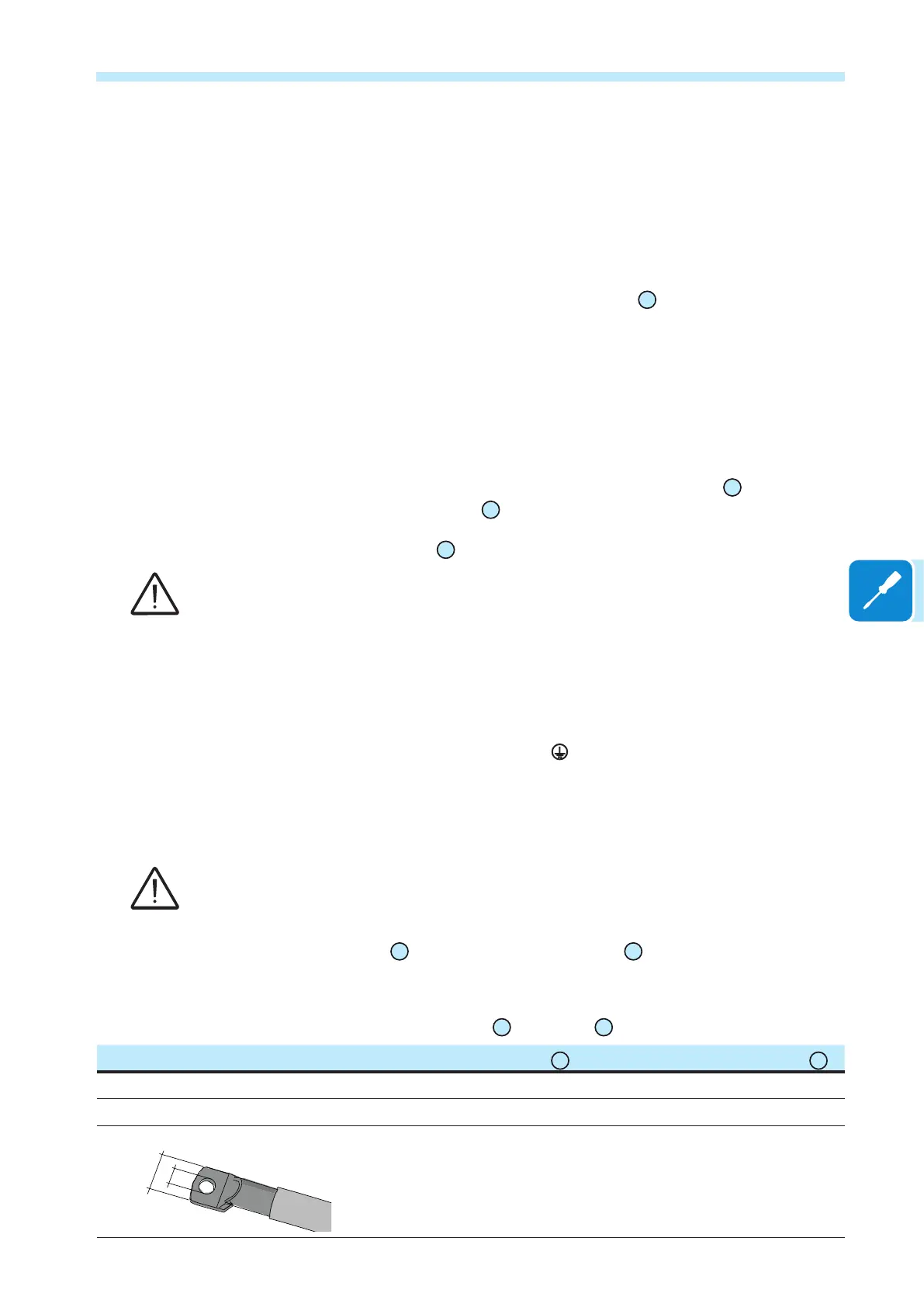
Cable lug dimensioning
b
a
for M10 Stud
a = 10.5 mm (min)
b = 40 mm (max)
for M8 Stud
a = 8.4 mm (min)
b = all dimension accepted