- 87 -
000839BG
5 - Installation
Connections to the communication and control board
The communication and control signals are connected to the
communication and control board inside the DC wiring box or directly to
the connectors on the external of the inverter. In particular, on the left side
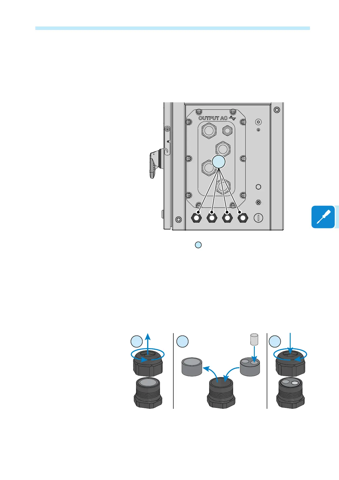
of the DC wiring box, there are:
12
- Four M25 cable glands
12
that can be used to reach the terminals /
connectors on the communication and control board. Each cable gland
accepts a cable (from 10 mm to 17 mm diameter).
As an alternative to each cable gland internal gasket the two-hole gasket
(supplied) could be installed:
The two-hole gasket accepts two cables with a diameter of 6mm; if a seal
hole is not to be used, it is necessary to install a plug (supplied plastic
cylinder) to ensure the inverter’s sealing.
If a cable gland will not be used, it will be necessary to leave (or install if
removed) the IP66 plastic cap of cable gland.