- 72 -
000835BG
5 - Installation
R
S
T
N
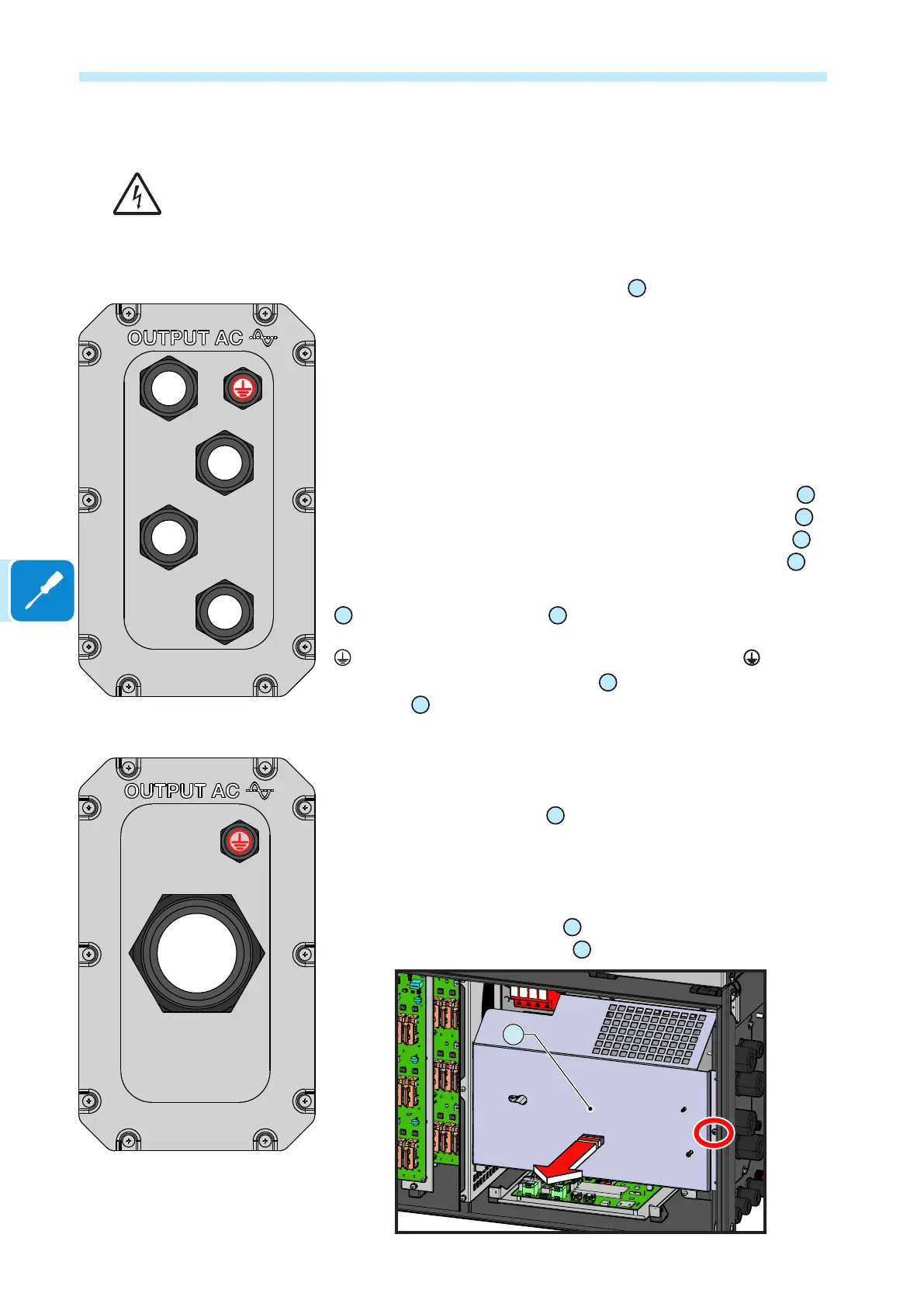
Single-core
AC panel version
R
S T
N
Multi-core
AC panel version (optional)
AC output cables connection
Before carrying out any operation, check that any external AC switch downstream to the
inverter (grid side) are in OFF position.
Routing of the AC cables inside the inverter must be carried out from the
right side of the inverter.
Depending of the version of the AC panel
11
installed on the inverter it
will be necessary to route the AC output and ground cables into different
ways:
- Single-core conguration (default): 4xM40 cable glands for the “R”,
“S”, “T” phases and for the “N” neutral cable and a M25 cable gland for
the grounding cable.
In this conguration the AC output and ground cables must be inserted
into the proper cable glands, trying to follow a logical order based on the
position of the internal connections:
R = Phase R (indicated with a label near the AC connection busbar
21
)
S = Phase S (indicated with a label near the AC connection busbar
21
)
T = Phase T (indicated with a label near the AC connection busbar
21
)
N = Neutral (indicated with a label near the AC connection busbar
21
)
The ground connection can be made using the Protective earth point (int.)
25
, Protective earth point (ext.)
10
or both (this is required by regulations
in force in certain countries of installation).
= Ground (indicated with the protective earth symbol near the
protection earth connection point (int.)
25
or protection earth connection
point (ext.)
10
).
- Multi-core conguration (optional): one M63 cable gland for the
“R”, “S”, “T” phases and for the “N” neutral cable and a M25 cable gland
for the grounding cable.
This version of the AC panel
11
could be can be ordered separately.
Refer to “Kit of recommended spare parts” chapter for further information.
Follow the procedure below to route all the requested cables:
• Open the wiring box front cover
07
.
• Remove the AC protective shield
27
by removing the M5 screw.
27