- 70 -
000835BG
5 - Installation
Characteristics and sizing of the line cable
The cross-section of the AC line conductor cables must be sized in order
to prevent unwanted disconnections of the inverter from the grid due to
high impedance of the line that connects the inverter to the power supply;
If the impedance is too high it causes an increase in the AC voltage which,
on reaching the limit set by the standards in the country of installation,
causes the inverter to switch off.
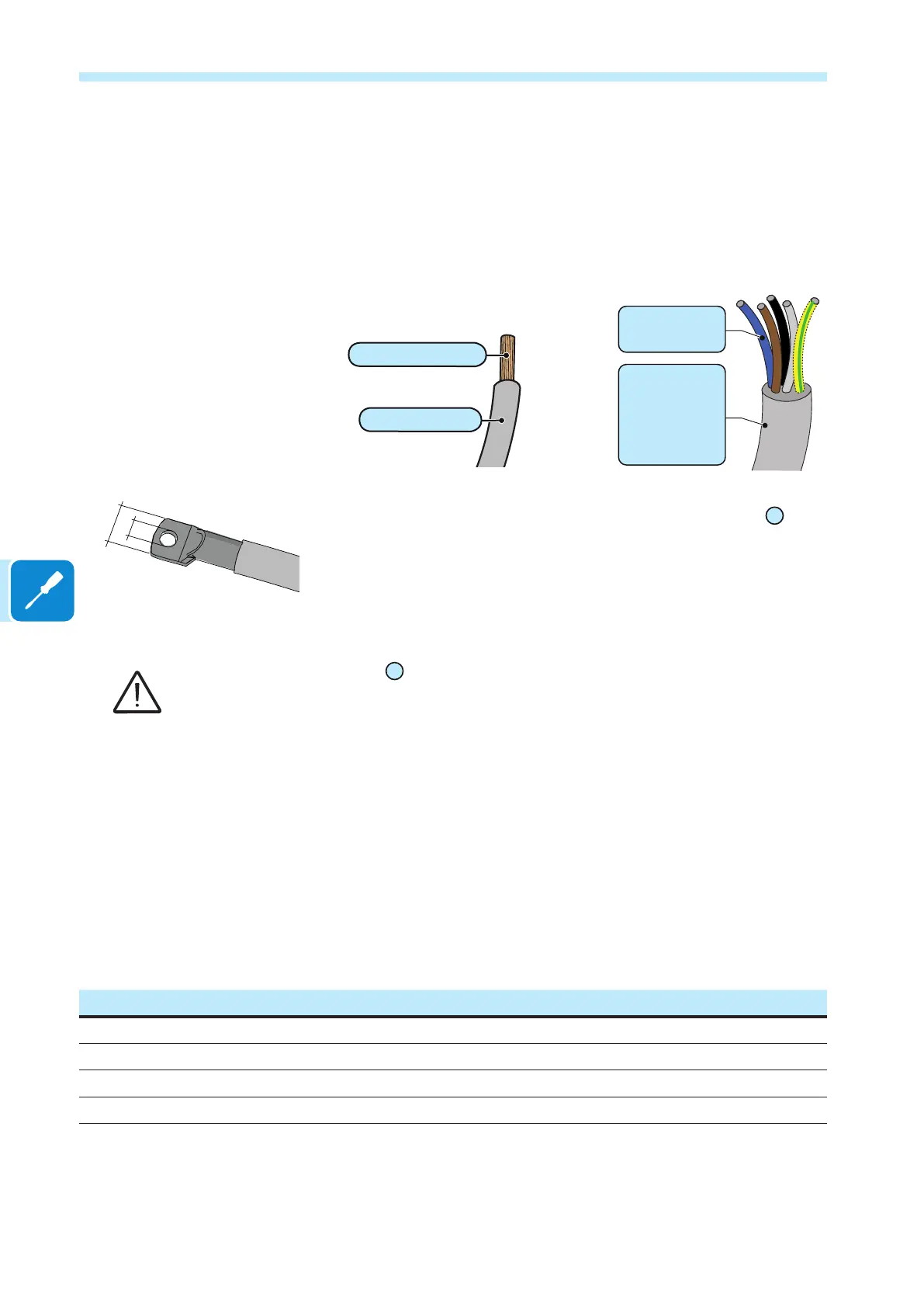
The AC cables must be connected to AC connection busbar
21
using
a cable lug (not supplied) of a suitable size for installation on the M10
screw used for securing the cable.
The AC output cable lugs must meet the following dimensions:
a = 10.5 mm (min) b = 40 mm (max)
The AC connection busbars
21
are in copper tin-plated; therefore if aluminum cables are used,
the correct coupling with the copper bars must be guaranteed by using appropriate bi-metallic
cable lug.
Load protection switch (AC disconnect switch)
To protect the AC connection line of the inverter, an overcurrent
protection device with the following features can be installed (these are
the caracteristic of a load protection switch referred to a single inverter
installation):
PVS-100-TL PVS-120-TL
Type Automatic circuit breaker with differential thermal-magnetic protection
Voltage/current rating min. 150 A / 400 V min. 150 A / 480 V
Magnetic protection characteristic B/C
Number of poles 3/4
b
a
max 185 mm²
19 - 28 mm
max 185 mm²
(each cable)
34 - 45 mm
or
37 - 53 mm
(depending on
AC cable gland)