22 Hardware description
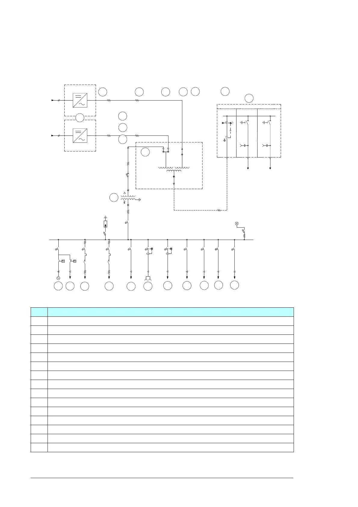
Main circuit diagram
The general single-line diagram depends on the configuration and options of the unit.
Refer to drawing 3AES-SH_4600-01-DW01.
No. Description
1 Inverters
2 Transformer
3 Switchgear
4 Auxiliary transformer
5 AC cabinet fan
6 AC cabinet heating
7 External fan 1 (transformer)
8 External fan 2 (transformer)
9Spare
10 Power socket 1 & 2
11 Lighting
12 Communication cabinet (customer)
13 MWS control equipment (temperature monitoring, transformer fan control and switchgear)
14 AC cabinet control system
15 Spare
A B C
F
G
E
D
H
I