-1.5 -1 -0.5 0 0.5 1 1.5
-1
-0.5
0
0.5
1
1.5
-
-
-
-
-
-
-
-
-
-
-
-
-
-
-
-
-
-
-
-
-
-
-
-
-
-
-
-
-
-
-
-
-
-
-
-
-
-
-
-
-
-
-
-
-
-
-
-
-
-
-
-
-
-
-
-
-
-
-
-
-
-
-
-
-
-
-
-
-
-
-
-
-
-
-
-
-
-
-
-
-
-
-
-
-
-
-
-
-
-
-
-
-
-
-
-
-
-
-
-
-
-
-
-
-
-
-
-
-
-
-
-
-
-
-
-
-
-
-
-
Real part (R) of Z in Ohms
Imaginary part (X) of Z in Ohms
^
^ ^
^ ^
^ ^
^
^ ^
^ ^
^ ^
^ ^
^
^
-
-
-
-
-
-
-
-
-
-
-
-
-
-
-
-
-
-
-
-
-
-
-
-
-
-
-
-
-
-
- -
-
-
-
-
-
-
-
-
-
-
-
-
-
-
-
-
-
-
-
-
-
-
-
-
-
-
-
-
-
-
0
1
Zone 1
Zone 2
The 1st
pole slip
occurred
relay
X in Ohms
The 2nd
pole slip
occurred
R in Ohms
RE
SE
2
3
to the 3rd
pole-slip
←
trajectory
of Z(R, X)
Pre-disturbance
normal load
Z(R, X)
0
→
pre-disturbance Z(R, X)
1
→
Z(R, X) under 3-phase fault
2
→
Z(R, X) when fault cleared
3
→
Z when pole-slip declared
lens determined
→
by the setting
StartAngle = 120°
limit of reach
→
IEC10000109-1-en.vsd
IEC10000109 V1 EN
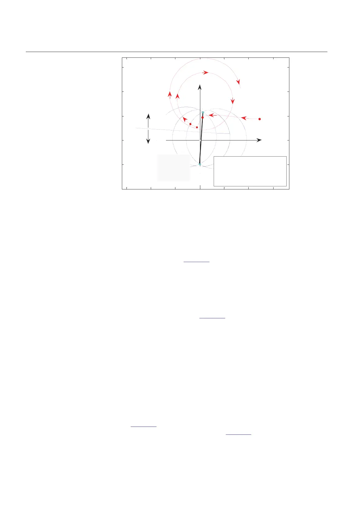
Figure 76: Loci of the complex impedance Z(R, X) for a typical case of generator
losing step after a short circuit that was not cleared fast enough
Under typical, normal load conditions, when the protected generator supplies the
active and the reactive power to the power system, the complex impedance Z(R, X) is
in the 1st quadrant, point 0 in Figure 76. One can see that under a three-phase fault
conditions, the centre of oscillation is at the point of fault, point 1, which is logical, as
all three voltages are zero or near zero at that point. Under the fault conditions the
generator accelerated and when the fault has finally been cleared, the complex
impedance Z(R, X) jumped to the point 2. By that time, the generator has already lost
its step, Z(R, X) continues it way from the right-hand side to the left-hand side, and the
1st pole-slip cannot be avoided. If the generator is not immediately disconnected, it
then continues pole-slipping — see
Figure 76, where two pole-slips (two pole-slip
cycles) are shown. Under out-of-step conditions, the centre of oscillation is where the
locus of the complex impedance Z(R, X) crosses the (impedance) line connecting the
points SE (Sending End), and RE (Receiving End). The point on the SE – RE line
where the trajectory of Z(R, X) crosses the impedance line can change with time and
is mainly a function of the internal induced voltages at both ends of the equivalent two-
machine system, that is, at points SE and RE.
Measurement of the magnitude, direction and rate-of-change of load impedance
relative to a generator’s terminals provides a convenient and generally reliable means
of detecting whether machines are out-of-phase step and pole-slipping is taking place.
Measurement of the rotor (power) angle δ is important as well.
Rotor (power) angle δ can be thought of as the angle between the two lines, connecting
point 0 in
Figure 76, that is, Z(R, X) under normal load, with the points SE and RE,
respectively. These two lines are not shown in Figure 76. Normal values of the power
angle, that is, under stable, steady-state, load conditions, are from 30 to 60 electrical
Section 7 1MRK 502 048-UEN A
Impedance protection
164
Technical manual