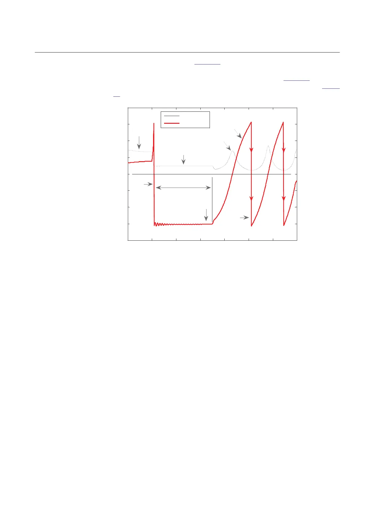
degrees. It can be observed in Figure 77 that the angle reaches 180 degrees when the
complex impedance Z(R, X) crosses the impedance line SE – RE. It then changes the
sign, and continues from -180 degrees to 0 degrees, and so on. Figure 77 shows the
rotor (power) angle and the magnitude of Z(R, X) against time for the case from
Figure
76.
0 200 400 600 800 1000 1200 1400
-4
-3
-2
-1
0
1
2
3
4
Time in milliseconds
→
Impedance Z in Ohm and rotor angle in radian
→
|Z| in Ohms
angle in rad
normal
load
fault 500 ms
Z(R,X) crossed
the impedance line, Z-line,
connecting points SE - RE
fault
occurrs
Z(R, X) under fault lies
on the impedance line
or near (for 3-ph faults)
Under 3-phase fault
condition rotor angle
of app. ±180 degrees
is measured ...
rotor (power)
angle
|Z|
IEC10000110-1-en.vsd
IEC10000110 V1 EN
Figure 77: Rotor (power) angle and magnitude of the complex impedance Z(R,
X) against the time
In order to be able to fully understand the principles of OOSPPAM, a stable case, that
is, a case where the disturbance does not make a generator to go out-of-step, must be
shown.
1MRK 502 048-UEN A Section 7
Impedance protection
165
Technical manual