1MAC309294-MB F Section 4
Protection functions
RER620 253
Technical Manual
4.5.4 Fault locator FLOC
4.5.4.1 Identification
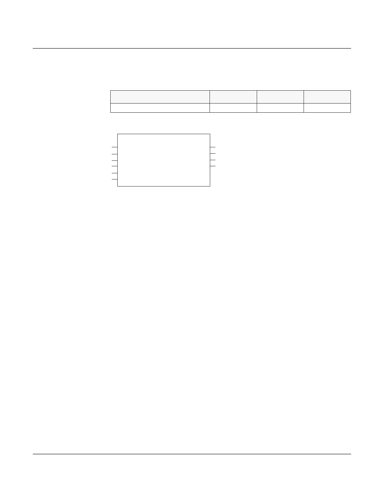
4.5.4.2 Function block
Figure 123: Function block
4.5.4.3 Functionality
The fault locator function performs the estimation of apparent distance to fault and fault
resistance. The calculation is performed by comparing the pre-fault current and voltage
phasor by fault current and voltage phasor along with line parameters.
The fault loop is determined and the respective voltage and current phasor are selected for
the fault location algorithm. The pre fault current and voltage phasor are used to calculate
the pre fault load impedance and fault current and voltage phasor are used to calculate the
apparent impedance during the fault. The load impedance, apparent impedance and line
parameters are used to estimate the fault resistance and distance to fault.
4.5.4.4 Operation principle
The Operation setting is used to enable or disable the function. When selected “On” the
function is enabled and respectively “Off” means function is disabled.
The operation of FLO can be described by using a module diagram (see Figure 124). All
the modules in the diagram are explained in the next sections.
Functional description IEC 61850
identification
IEC 60617
identification
ANSI/IEEE C37.2
device number
Fault locator DRFLO FLO FLO
V_A
V_B
V_C
I_
A
I_B
I_C
FLT_DIST
FLT_R
FLT_LOOP
FLO
XF_LOOP