1MAC309294-MB F Section 5
Control functions
RER620 333
Technical Manual
differences are indicated in the LHMI. At the same time, it is recommended to check the
voltage difference and the frequency differences presented in the Monitored data view.
These values should be within the permitted tolerances, that is, close to zero.
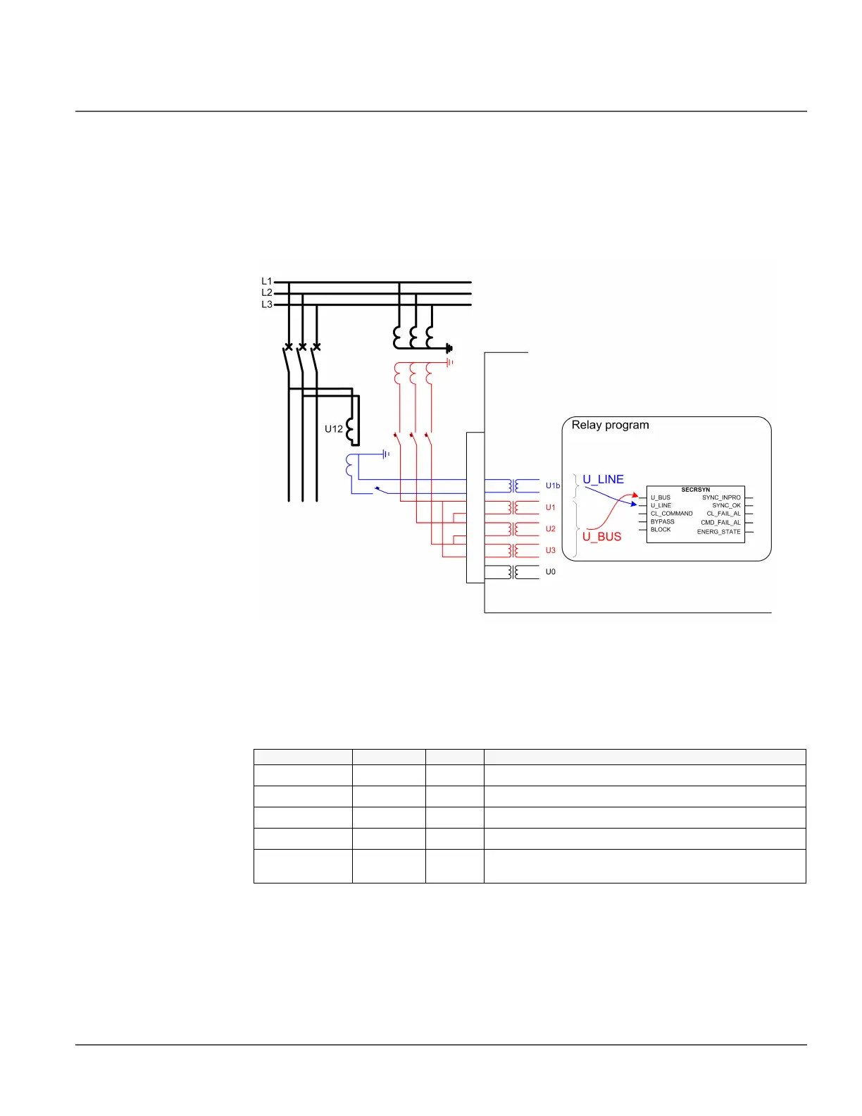
Figure 176 shows an example where the synch-check is used for the circuit breaker closing
between a busbar and a line. The phase-to-phase voltages are measured from the busbar
and also one phase-to-phase voltage from the line is measured.
Figure 176: Connection of voltages for the relay and signals used in synch-check
5.3.6 Signals
Table 305: 25 input signals
Name Type Default Description
V_BUS SIGNAL 0 Busbar voltage
V_LINE SIGNAL 0 Line voltage
CL_COMMAND BOOLEAN 0=False External closing request
BYPASS BOOLEAN 0=False Request to bypass synchronism check and voltage check
BLOCK BOOLEAN 0=False Blocking signal of the synch check and voltage check
function