1MAC309294-MB F Section 3
Basic functions
RER620 55
Technical Manual
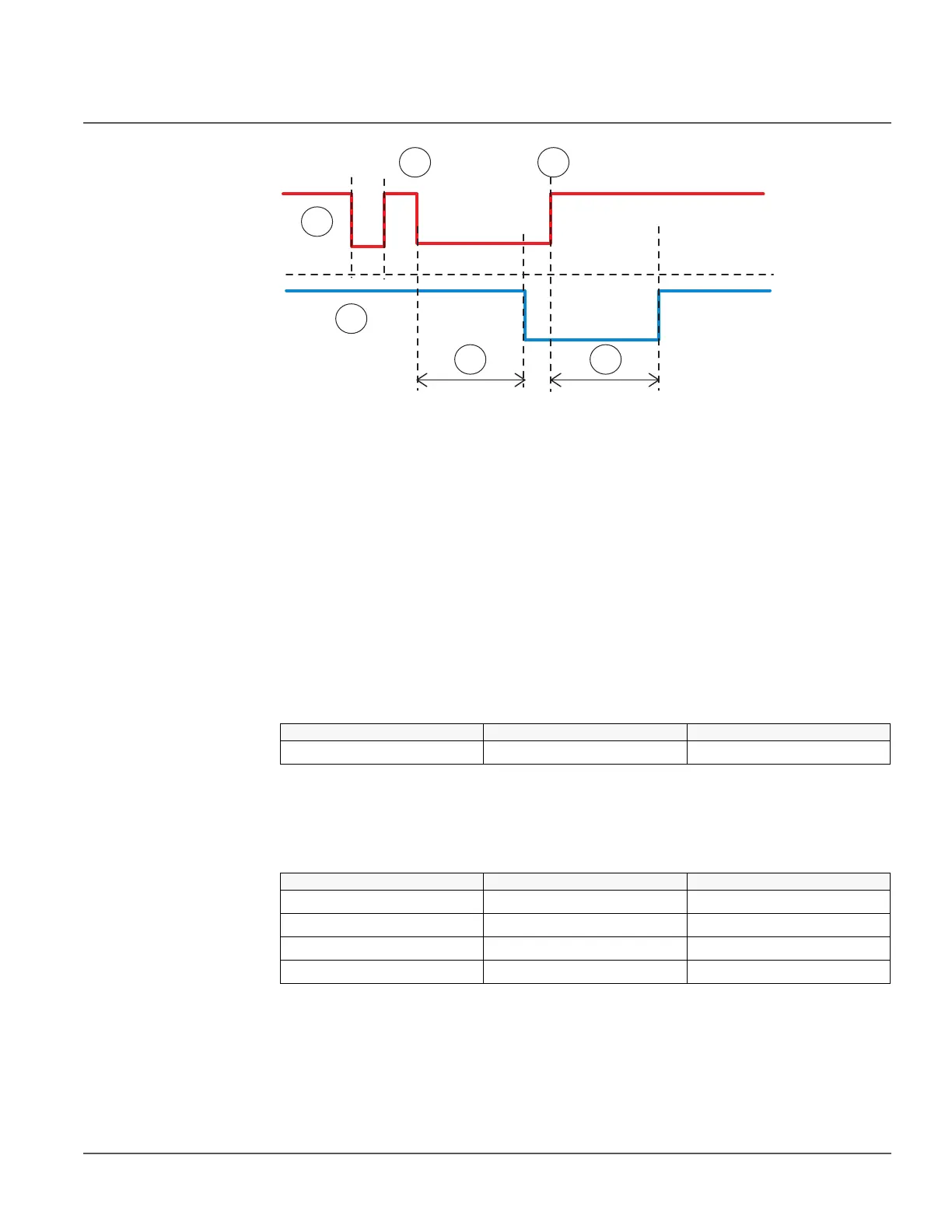
Figure 8: Binary input filtering
1t
0
2t
1
3 Input signal
4 Filtered input signal
5 Filter time
At the beginning, the input signal is at the high state, the short low state is filtered and no
input state change is detected. The low state starting from the time t
0
exceeds the filter
time, which means that the change in the input state is detected and the time tag attached
to the input change is t
0
. The high state starting from t
1
is detected and the time tag t
1
is
attached.
Each binary input has a filter time parameter Input # filter, where # is the number of the
binary input of the module in question (for example Input 1 filter).
Table 36: Input filter parameter values
3.8.2 Binary input inversion
The parameter Input # invert is used to invert a binary input.
Table 37: Binary input states
When a binary input is inverted, the state of the input is TRUE (1) when no control voltage
is applied to its terminals. Accordingly, the input state is FALSE (0) when a control
voltage is applied to the terminals of the binary input.
Parameter Values Default
Input # filter 1...15000 ms 5 ms
Control voltage Input # invert State of binary input
No 0 False (0)
Yes 0 True (1)
No 1 True (0)
Yes 1 False (0)