1MAC309294-MB F Section 4
Protection functions
RER620 127
Technical Manual
The timer calculates the pickup duration (PICKUP_DUR) value which indicates the
percentual ratio of the pickup situation and the set trip time. The value is available through
the Monitored data view.
Blocking logic
There are three operation modes in the blocking functionality. The operation modes are
controlled by the BLOCK input and the global setting “Configuration/System/Blocking
mode” which selects the blocking mode. The BLOCK input can be controlled by a binary
input, a horizontal communication input or an internal signal of the relay program. The
influence of the BLOCK signal activation is preselected with the global setting Blocking
mode.
The Blocking mode setting has three blocking methods. In the “Freeze timers” mode, the
trip timer is frozen to the prevailing value. In the “Block all” mode, the whole function is
blocked and the timers are reset. the “Block TRIP output” mode, the function operates
normally but the TRIP output is not activated.
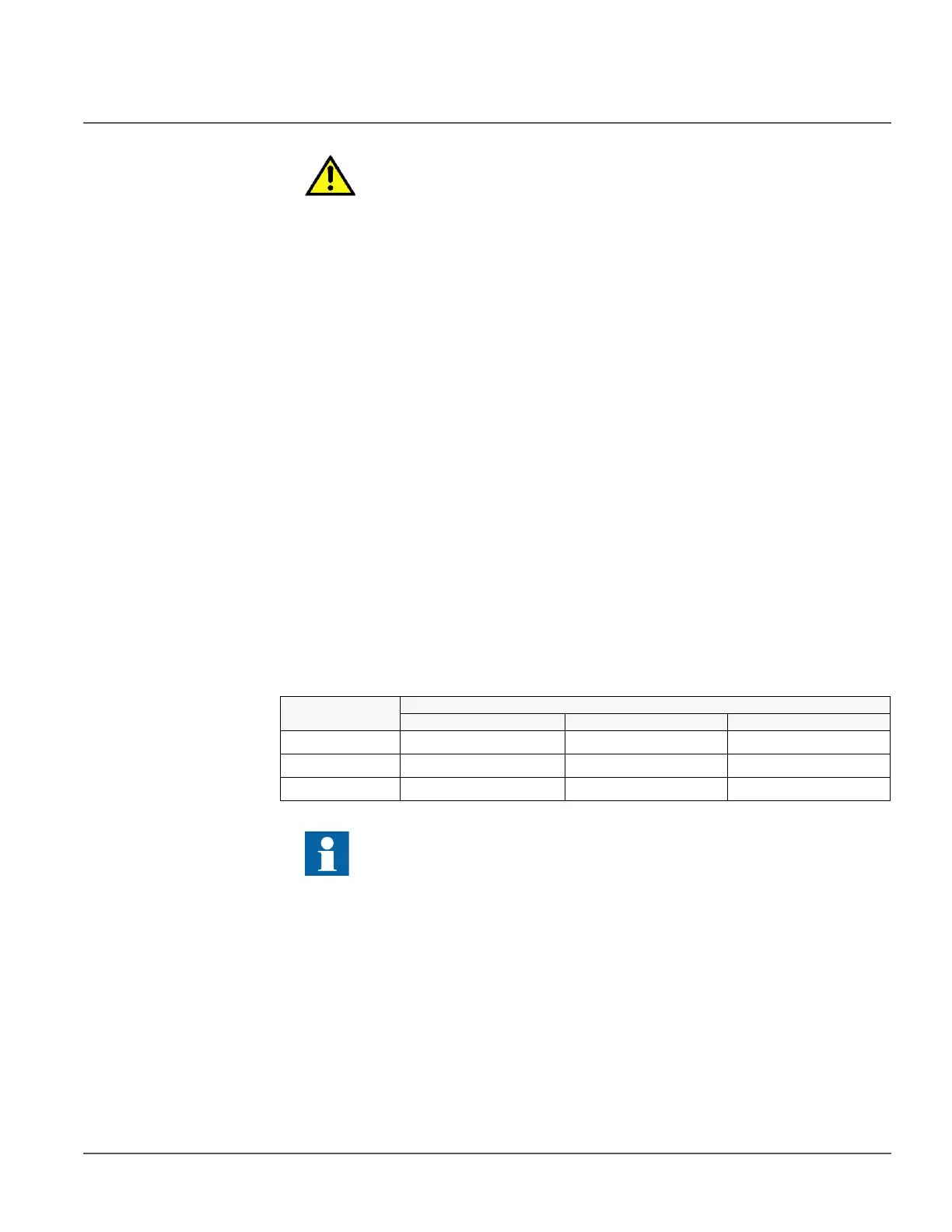
4.1.3.5 Measurement modes
The function operates on three alternative measurement modes: “RMS”, “DFT” and
“Peak-to-Peak”. The measurement mode is selected with the Measurement mode setting.
Table 143: Measurement modes supported by 51N/50N or 51G/50G stages
4.1.3.6 Timer characteristics
51N/50N or 51G/50G supports both DT and IDMT characteristics. The user can select the
timer characteristics with the Operating curve type and Type of reset curve settings. When
the DT characteristic is selected, it is only affected by the Trip delay time and Reset delay
time settings.
The relay provides 16 IDMT characteristics curves, of which seven comply with the IEEE
C37.112 and six with the IEC 60255-3 standard. Two curves follow the special
characteristics of ABB praxis and are referred to as RI and RD. In addition to this, a user
programmable curve can be used if none of the standard curves are applicable. The user
The Minimum trip time setting should be used with great care because the
operation time is according to the IDMT curve, but always at least the value
of the Minimum operate time setting. For more information, see the
General function block features section in this manual
Measurement
mode
Supported measurement modes
51N/G 50N/G-1/2 50N/G-3
RMS x x
DFT x x
Peak-to-Peak x x x
For a detailed description of the measurement modes, see the General
function block features section in this manual.