1MAC309294-MB F Section 12
Relay physical connections
RER620 553
Technical Manual
Section 12 Relay physical connections
All external circuits are connected to the terminals on the rear panel of the relay.
• Connect each signal connector (X100 and X110) terminal with one 14 or 16 Gauge
wire. Use 12 or 14 Gauge wire for CB trip circuit.
• Connect each ring-lug terminal for signal connector X120 with one of maximum 14
or 16 Gauge wire.
• Connect each ring-lug terminal for CTs/VTs with one 12 Gauge wire.
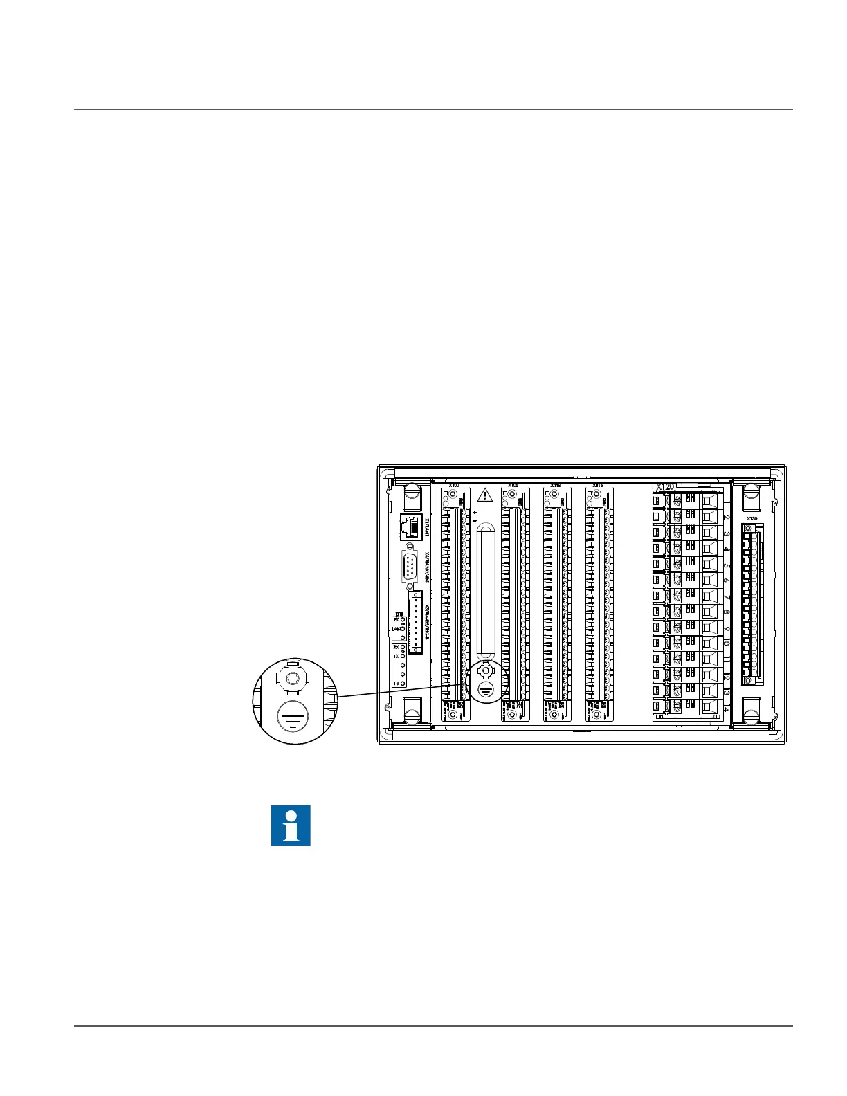
12.1 Protective ground connections
Figure 313: The protective ground screw is located between connectors X100 and
X105
12.2 Communication connections
The front communication connection is an RJ-45 type connector used mainly for
configuration and setting.
Depending on order code, several rear port communication connections are available.
The ground lead must be at least 4.0 mm
2
and as short as possible.