1MAC309294-MB F Section 4
Protection functions
RER620 207
Technical Manual
4.3.3.4 Operation principle
The function can be enabled and disabled with the Operation setting. The corresponding
parameter values are Enable and Disable.
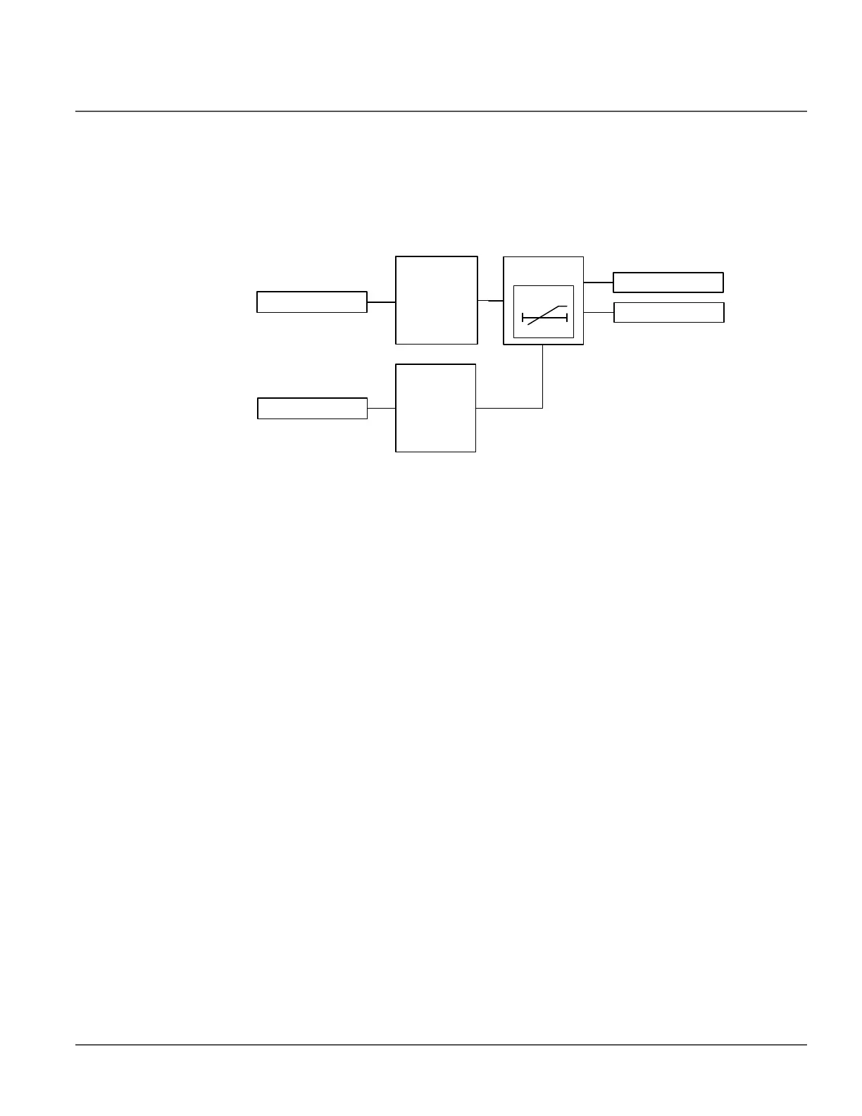
The operation of residual overvoltage protection can be described by using a module
diagram. All the blocks in the diagram are explained in the next sections.
Figure 94: Functional module diagram. V
N
represents the zero sequence voltage.
Level detector
The measured or calculated zero sequence voltage is compared with the set Pickup value.
If the value exceeds the set Pickup value, the level detector sends an enable-signal to the
timer.
Timer
Once activated, the timer activates the PICKUP output. The time characteristic is
according to DT. When the trip timer has reached the value set by Trip delay time, the
TRIP output is activated. If the fault disappears before the module trips, the reset timer is
activated. If the reset timer reaches the value set by Reset delay time, the trip timer resets
and the PICKUP output is deactivated.
The timer calculates the pickup duration (PICKUP_DUR) value which indicates the ratio
of the pickup situation and the set trip time. The value is available through the Monitored
data view.
Blocking logic
There are three operation modes in the blocking functionality. The operation modes are
controlled by the BLOCK input and the global setting “Configuration/System/Blocking
mode” which selects the blocking mode. The BLOCK input can be controlled by a binary
input, a horizontal communication input or an internal signal of the relay program. The
influence of the BLOCK signal activation is preselected with the global setting Blocking
mode.
The Blocking mode setting has three blocking methods. In the “Freeze timers” mode, the
trip timer is frozen to the prevailing value. In the “Block all” mode, the whole function is
V
N
BLOCK
Level
detector
TRIP
PICKUP
Blocking
logic
t
Timer