1MAC309294-MB F Section 2
RER620 overview
RER620 27
Technical Manual
Table 2: Characters and rows on the view
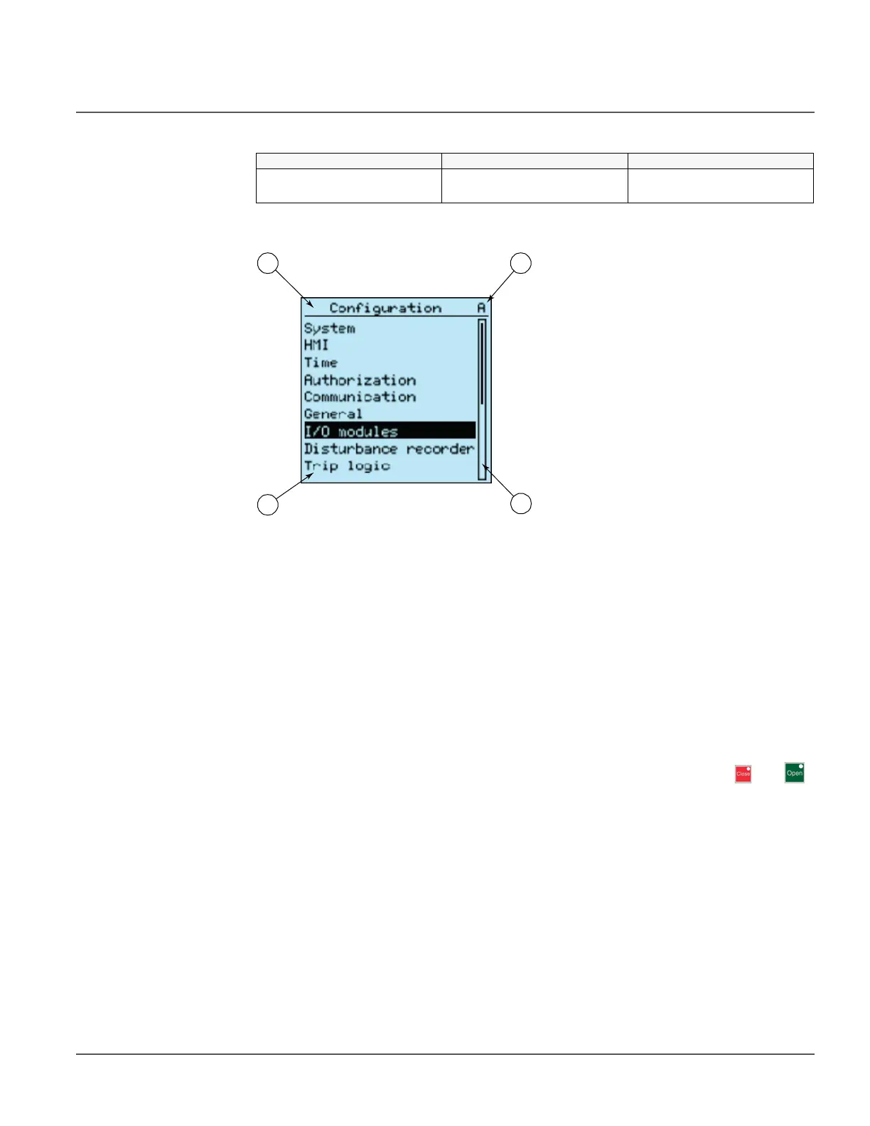
The display view is divided into four basic areas.
Figure 4: Display layout
1 Header
2Icon
3 Content
4 Scroll bar (displayed when needed)
2.2.2 LEDs
The LHMI includes three protection indicators above the display: Normal, Pickup and
Trip.
There are also 11 matrix programmable alarm LEDs on front of the LHMI. The LEDs can
be configured with PCM600 and the operation mode can be selected with the LHMI,
WHMI or PCM600.
There are two additional LEDs which are embedded into the control buttons and .
They represent the status of the circuit breaker.
2.2.3 Keypad
The LHMI keypad contains push-buttons which are used to navigate in different views or
menus. With the push-buttons you can give open or close commands to one primary
object, for example, a circuit breaker, disconnector or switch. The push-buttons are also
used to acknowledge alarms, reset indications, provide help and switch between local and
remote control mode.
Character size Rows in view Characters on row
Large, variable width (13x14
pixels)
4 rows
8 rows with large screen
min 8