1MAC309294-MB F Section 9
Other functions
RER620 433
Technical Manual
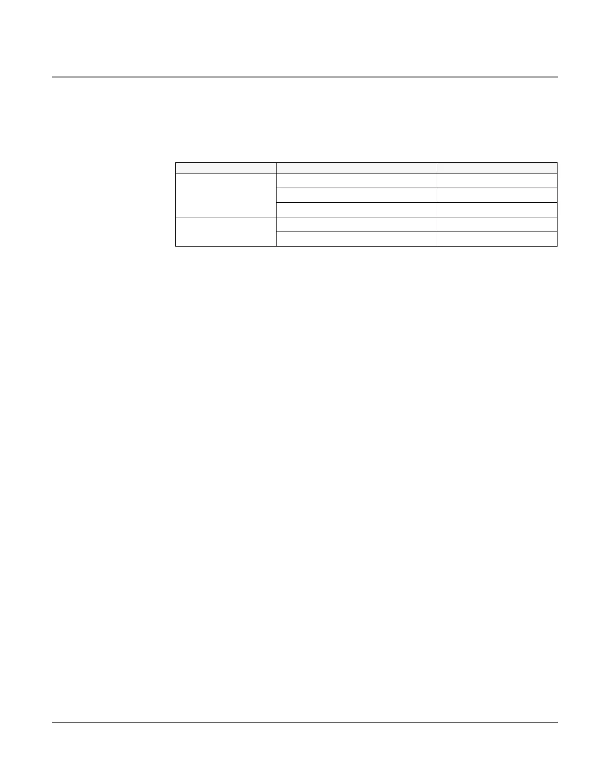
The CVD Voltage Clamping function is based on the following table, where V1x, x=a,b,c,
are the CVD voltage measurements, V2x, x=a,b,c, are the reference PT voltage
measurements, and V2n is the nominal voltage defined in the relay structure,
Configuration-> Analog inputs->Voltage 2-> Secondary voltage.
Table 387: Clamping logic
When enabling the CVD Voltage Clamping function, the following assumptions and
limitations exist:
1. The Clamping function is applicable only for the Wye-connected PT installation,
single or three phase.
2. For single phase PT installation, the CVD clamping is applicable only to a nominal
120Vac low voltage cabinet control power.
3. For single phase PT installation, the voltage based protections and measurement
alarms on the reference side should be disabled.
4. The Clamping function affects only the voltage amplitudes.
5. When no reference voltage is available, the Clamping function should be disabled;
otherwise, V1 will report the actual CVD values when the poles are open and report
zeroes when the poles are closed.
6. If both V1 and V2 are CVDs or both are PTs, the voltages measurements will not be
adjusted.
7. It is recommended that voltage based protections are either not used or blocked
when the Clamping function is enabled.
Recloser Position Justification Conditions Adjusted CVD Measurements
Closed V1x > 1.04*V2x V1x = 1.04*V2x
0.85*V2x ≤ V1x < 0.96*V2x V1x = 0.96*V2x
All other conditions No clamping
Open V2x ≥ 0.90*V2n AND V1x > 1.04*V2x V1x = 1.04*V2x
All other conditions No clamping