31Connecting a control cable in accordance with VDE AR-N 4100
Please follow these steps to set up the data cabling in the Wallbox eM4Single:
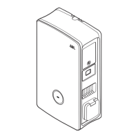
1 Connect the RJ45 plug of the data cable to the LAN interface
of the communication module.
Reset
16 mm 85 mm
DATA
NOTE
Continuation of the wiring diagram
Connect all wallboxes in the charging group via their LAN interfaces. To bring together all wallboxes, they must be connected
centrally to a router or switch in the local network infrastructure.
x For interference suppression in the low-frequency range, you must attach the supplied folding ferrite to a cable loop in the data
line. It is recommended that you lay the cable loop outside the housing and lay it on the rear of the wallbox during installation.
x If the wallbox is already installed, you can also connect the cable loop with the folding ferrite inside the wallbox.
Connecting a control cable in accordance with VDE AR-N 4100
According to the Application Rule VDE AR-N 4100, a wallbox must oer the possibility of remote disconnection by the local energy
supplier. The Wallbox eM4Single oers a contact for this purpose, which is located in the right-hand area of the main module behind
the communication module (see also “External load shedding in accordance with VDEAR-N4100” onpage18).
The following requirements apply to the control cable:
x Solid conductor, 0.5 to 1.5mm², stripping length: 9mm
x Fine-stranded conductor, 0.5 to 1.5mm² / 0.5 to 1.0mm² with ferrules, stripping length: 9mm
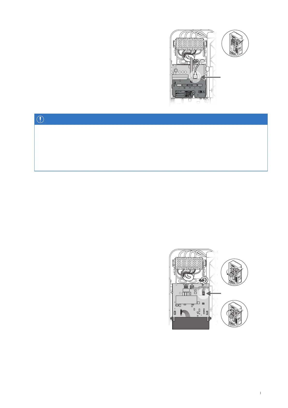
Proceed as follows to connect the control cable to the Wallbox eM4Single:
1 Open the communication module to the front.
EXT.
CONTROL
2 Connect the control cable inserted via the EXT.CONTROL
grommet to the terminal EN1.
3 Fold the communication module back up so that it clicks into
place.
After establishing the electrical connection of the control cable, the remote disconnection function must be activated via the ABL
Configuration App. To do this, please refer to the sections starting on page39.
 Loading...
