10 Introduction to the Wallbox eM4Single
The Wallbox eM4Single at a glance
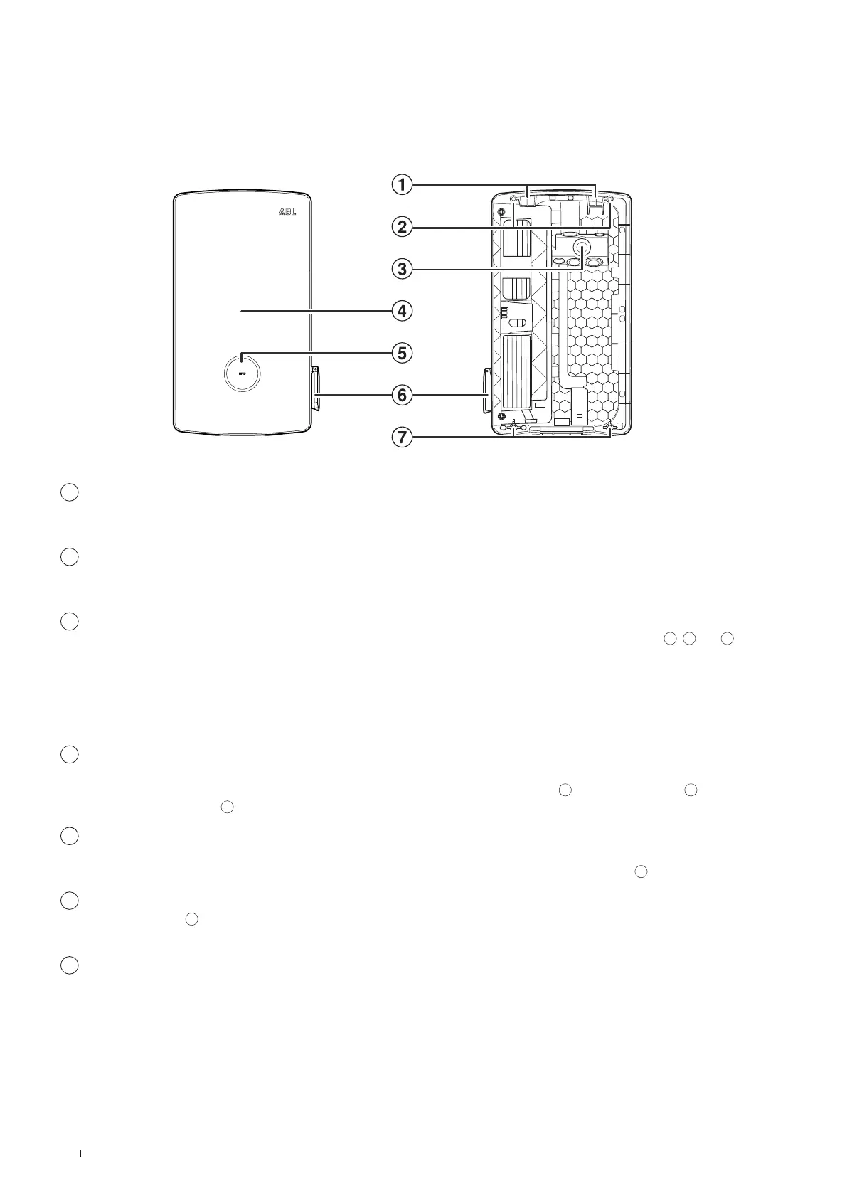
The Wallbox eM4Single is designed as follows:
Front and rear view
The following illustration shows the front and rear of the Wallbox eM4Single.
Front Rear
1
Suspension points
Use these two suspension points on the upper edge of the rear to hang the eM4Single in the mounting rail (included in delivery)
screwed to the mounting position (see “Preparing and fixing the wallbox in place” onpage27).
2
Attachment points for mounting rail
The wallbox is fixed in place by screwing it into the mounting rail using the two upper attachment points (see page28). The
corresponding screws are supplied.
3
Supply cable area
The supply cable area has three large grommets for inserting a power line from above, below or behind, marked
A
,
B
and
C
on the drilling template.
The two smaller grommets are used for inserting a data cable for communication within a charging group or to lay a control
cable in accordance with VDE AR-N 4100. These two inlets are marked DATA and EXT. CONTROL on the drilling template.
All grommets in the supply cable area are designed as "push-out" membranes and can be pierced directly with the cable (see
“Inserting the power and data cables” onpage24).
4
Housing cover
The housing cover protects the internal electronic components (see next figure) from unauthorised access and must always be
closed and locked during operation. The housing cover is locked/unlocked via the RCCB flap
12
of the power module
15
(right
side) and the key opening
8
on the underside (left side).
5
Status display with RFID reader
The circular status indicator shows the states of the charge point by means of a multi-coloured LED ring. The RFID reader
module for authorising the charging process is located centrally behind the status indicator (see also point
16
).
6
Type 2 charging socket
The power module
15
of the Wallbox eM4Single has a type 2 charging socket for connecting an IEC 62196-1 and IEC 62196-2
certified charging cable, which can be purchased as an accessory from ABL (see “Accessories” onpage19).
7
Wall mounting point
The wallbox is fixed in place by screwing it into the wall using the two lower attachment points (see page28). The corre-
sponding screws are supplied.
 Loading...