12 Introduction to the Wallbox eM4Single
13
MID-compliant energy meter
The MID-compliant energy meter displays various information on the charging operation. You can find further information on
this topic in section “Information displayed in the energy meter” onpage14.
14
Communication module
The communication module provides a LAN interface for data cabling in a charging group and a USB port (Controller wallbox
only) for the supplied LTE USB stick for wireless communication with a backend (see “Preparing and installing the LTE USB
stick” onpage32).
In the upper left area of the communication module, there is access to the reset push button marked with a screwdriver
and the word Reset, which allows the wallbox to be reset (see “Resetting the wallbox and restoring to factory settings”
onpage54).
In addition, the communication module can be flipped forward, allowing access to contact EN1 for connecting a control cable in
accordance with VDEAR-N4100 (see “Connecting a control cable in accordance with VDE AR-N 4100” onpage31).
15
Power module
The power module integrates the components for the charge point, including the RCCB, DC residual current detection, the
contactor, the MID-compliant energy meter
13
and the Type 2 charging socket
6
.
16
HMI module
The HMI (Human Machine Interface) module of the wallbox displays the various states of the electronic components for moni-
toring and determining the status of the charge points via a multi-coloured LED ring and an acoustic signal generator (see next
section).
It also includes the RFID reader module for authorising the charging processes, provided that the wallbox was configured
accordingly during installation or is operated with a backend. The RFID function is set up via the ABL Configuration App (see
“Configuring the Wallbox eM4Single” onpage35).
How the HMI works
The Human Machine Interface of the Wallbox eM4Single informs the user about the current status of the wallbox or charge point.
Visual feedback is provided by an LED ring with dierent colour and movement patterns. The wallbox also emits sound signals for
selected functions.
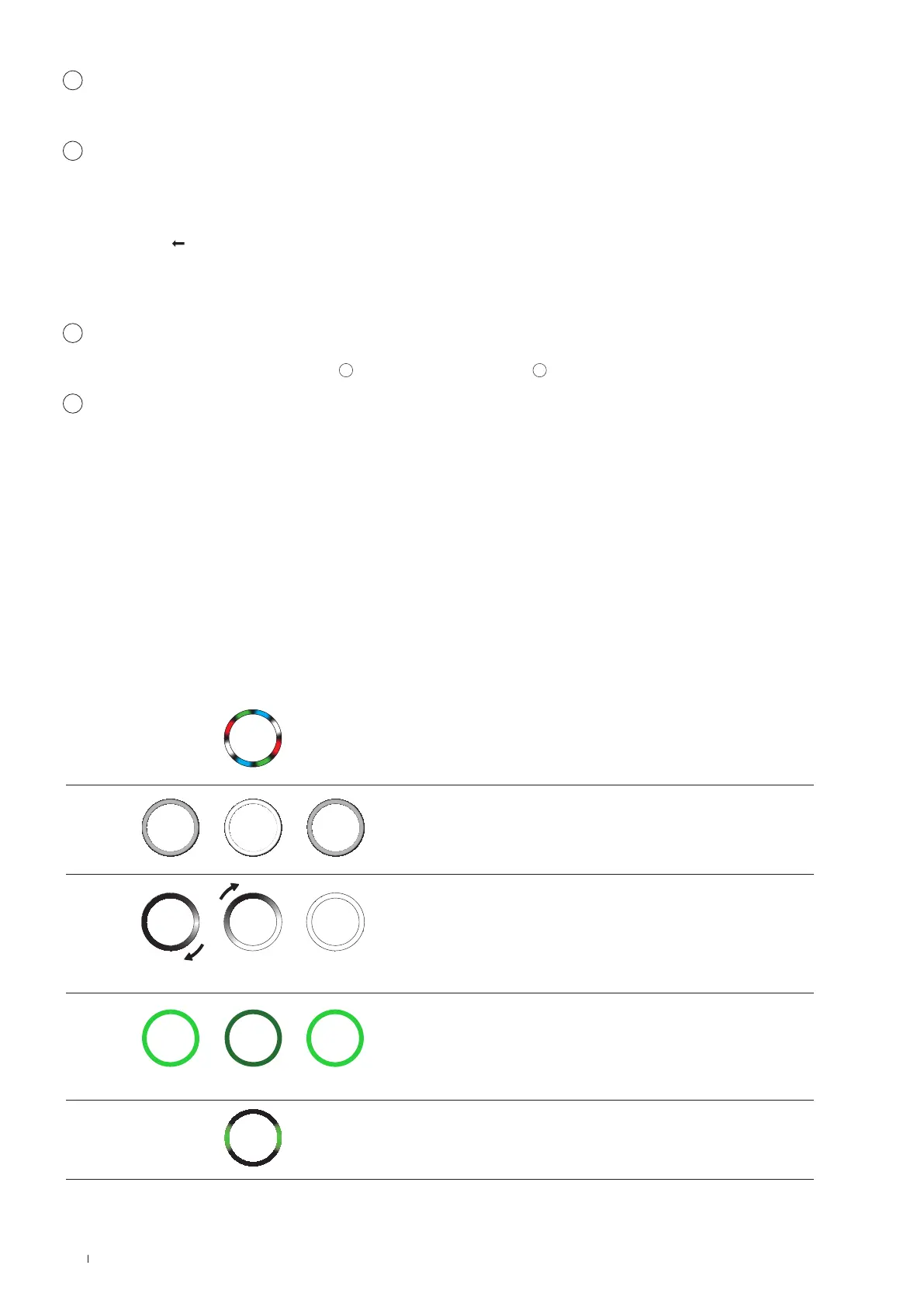
The following table shows the HMI signal and its corresponding functional status:
Boot process active
When the Wallbox eM4Single is connected to the electricity
grid or restarted during setup, it starts the boot process: The
LEDs light up green, blue, white and red for 5 seconds.
Missing or active configuration
If the wallbox has not yet been set up via the ABL Configu-
ration App during first use or if the setup is currently being
performed, the LED circle pulsates white.
Completing the configuration
Once the setup has been completed in the ABL Configuration
App and transferred to the wallbox, the LEDs light up white one
after the other in a clockwise direction until finally the entire LED
ring is lit up white continuously for a short moment.
Ready for charging
In normal operation, the status indicator pulsates green to indi-
cate readiness for charging.
Vehicle connected and recognised
When a vehicle is connected and recognised, the status indicator
lights up static green.
 Loading...