P5271/P5290/P5390W/P5271i Condential
2-6
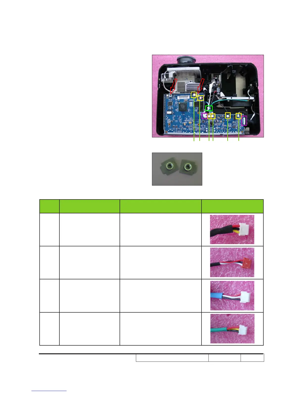
3. Remove 2 Main Board Shielding Bottom
Bracket (as red arrows point).
4. Cut off the cable tie (as green square).
5. Unplug 2 connectors (as purple square)
to disassemble the Color Wheel cable
and Lamp Driver to Main Board cable.
6. Unplug 6 connectors (as yellow square).
Please refer to the table as below for
details of each connector
Item
Male Connector
on Main Board
The key feature Figure
A IR
Compose of Red/Black/Yellow
Wire and Black wire tube (3 pin)
B Photo Sensor
Compose of Red/White/Black
Wire , Red Connector and Black
wire tube (3 pin)
C Blower
Compose of Red/Black/White
Wire and Blue wire tube (3 pin)
D System Fan
Compose of Red/Yellow/Black
Wire and Green wire tube (3 pin)
A EDCB F
Bracket