Ferroresonant L-828/L-829 CCR Installation
2009 ADB Airfield Solutions, Incorporated
96A0288T 3-2
All rights reserved Issued 9/04
To install wiring, perform the following procedure:
1. Verify the input supply voltage corresponds to the voltage rating on
the nameplate of the regulator.
2. Make sure the front panel rotary selector switch is set to the OFF
position.
3. Ground the regulator by making an adequate ground wire (AWG 6 or
larger) connection to the external earth ground lug on the regulator.
4. An appropriate disconnect-type cutout or circuit breaker shall be
provided outside the regulator for the input power supply lines.
5. Short-circuit the output terminals TB2-1, TB2-2 using 8 AWG
minimum wire to avoid lamp destruction in case of excessive current
output.
6. Install appropriate external lightning arrestors on the input power
supply lines as close as possible to the CCR’s input fuse block F1/F2,
or terminal block TB3, whichever is present.
7. Refer to Table 2-3 for the recommended input wire. Connect the
power supply lines from the disconnect switch or main circuit breaker
to the CCR input fuse block F1/F2 or terminal block TB3. Tighten all
connections.
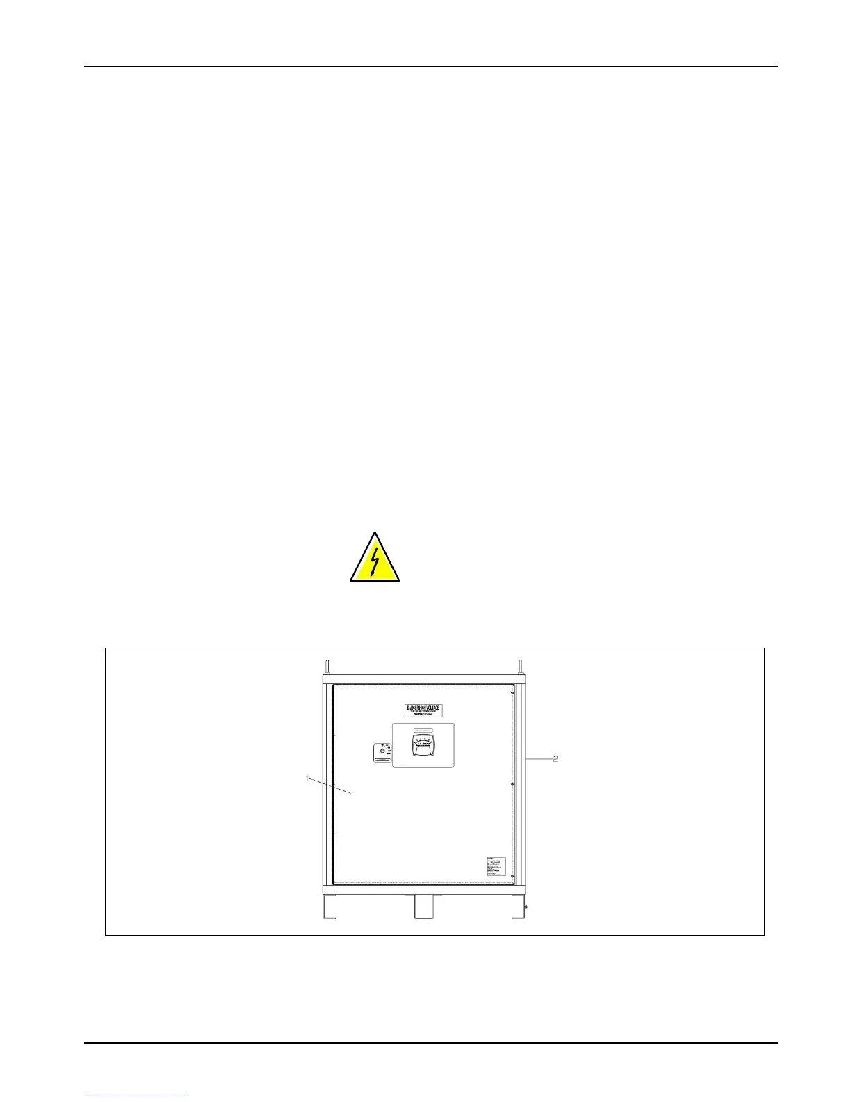
WARNING: Place wiring for output, input, and Remote control
only on the right side of the CCR to prevent damage to the PCB
that is located on the front Left side of the enclosure. If output,
input, and remote control wiring must enter from the left side of
the enclosure then wiring must be then routed through conduit where it
passes the PCB area. See Figure 3-1.
Figure 3-1 Wiring on Right Side of CCR
2. Place Conduit and Wire on Right Side of CCR
Wiring Connections and
Startup (contd.)
 Loading...