Ferroresonant L-828/L-829 CCR Installation
2009 ADB Airfield Solutions, Incorporated
96A0288T 3-3
All rights reserved Issued 9/04
8. Engage main circuit breaker or disconnect switch to energize the
regulator.
9. Turn front panel rotary selector switch to all brightness steps, and
verify that current values on the panel ammeter correspond to those in
Table 2-9 for each brightness step.
10. Disengage the main current breaker or disconnect switch to de-
energize the regulator.
11. Turn the rotary selector switch to OFF.
12. Connect remote control lines, if required, to remote control terminal
block TB1. Use AWG 19, 300 V wire or larger as indicated in Table
3-3 for 120 Vac signals. See Figure 8-1 in the Wiring Schematics
section for remote control connections.
NOTE: If the ADB Airfield Solutions Advanced Control Equipment
is used with the ferroresonant L-828 CCR, refer to the Advanced
Control Equipment manual (96A0245) for wiring connections to
remote control.
NOTE: Tables 3-1 through 3-3 provide the necessary connections for
remote control. Terminal B1 (B10) does not need to be wired.
Brightness step B1 (B10) occurs when the regulator is switched on.
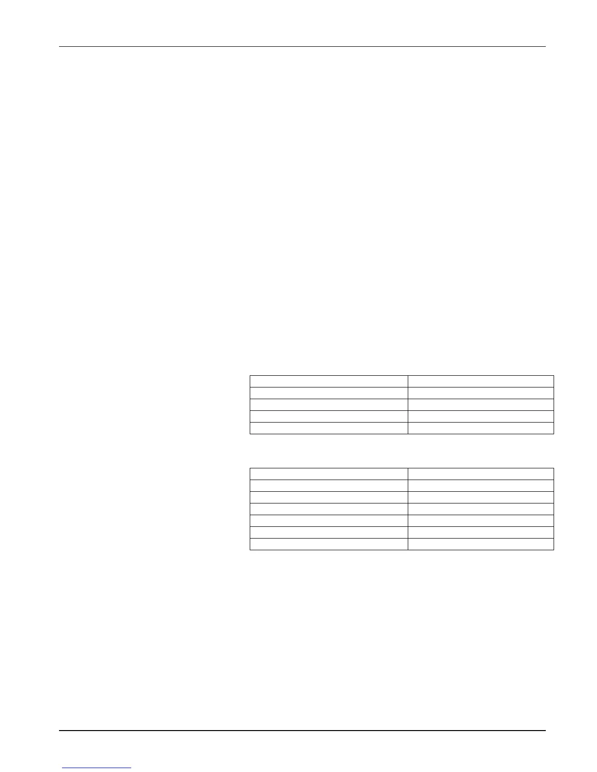
Table 3-1 Remote 120 Vac Control Connections (3-Step/6.6 A)
For this remote intensity step…
Table 3-2 Remote 120 Vac Control Connections (5-Step/6.6 A)
For this remote intensity step…
Wiring Connections and
Startup (contd.)
 Loading...