Ferroresonant L-828/L-829 CCR Installation
2009 ADB Airfield Solutions, Incorporated
96A0288T 3-4
All rights reserved Issued 9/04
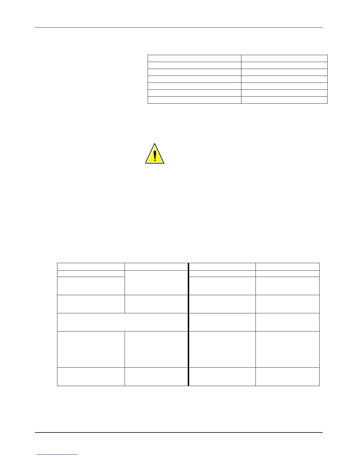
Table 3-3 Remote 120 Vac Control Connections (5-Step/20 A)
For this remote intensity step…
13. Make sure wiring connections are tight and no wires are shorting
across each other.
CAUTION: Incorrect wiring can damage regulator. Double
check all connections.
14. Energize regulator and set rotary selector switch to REM. Operate the
CCR by remote control, and verify correct current levels are obtained
on all brightness steps.
15. Turn rotary selector switch to OFF and de-energize regulator
(disengage disconnect switch or main circuit breaker). Remove short-
circuit link between output terminals TB-2-1 and TB2-2.
16. Connect the 6.6 A or 20 A series lighting circuit to the output
terminals/ bushings and tighten all connections.
Table 3-4 Input/Output Connections
front of component plate
right hand side
CCF 30kW/208
CCF 30kW/208
and VR2) on Back of
Front of component plate
component plate
N/A
and VR2) on Back of
Front of component plate
right hand side Top of each
Fuse Block front of
component plate right hand
and VR2) on Back of
component plate
front of component plate
and VR2) on Back of
Wiring Connections and
Startup (contd.)
 Loading...