Ferroresonant L-828/L-829 CCR Operation
2009 ADB Airfield Solutions, Incorporated
96A0288T 4-5
All rights reserved Issued 9/04
NOTE: Make sure the meter is set on the AC current scale.
NOTE: Because the output current waveform is not a true sine wave,
the ammeter must be of the true-rms type. Field instruments such as
clamp-on ammeters and Simpson voltmeters will give erroneously low
readings.
2. Energize the regulator locally, and set the rotary selector switch to the
maximum brightness position S5 or B100.
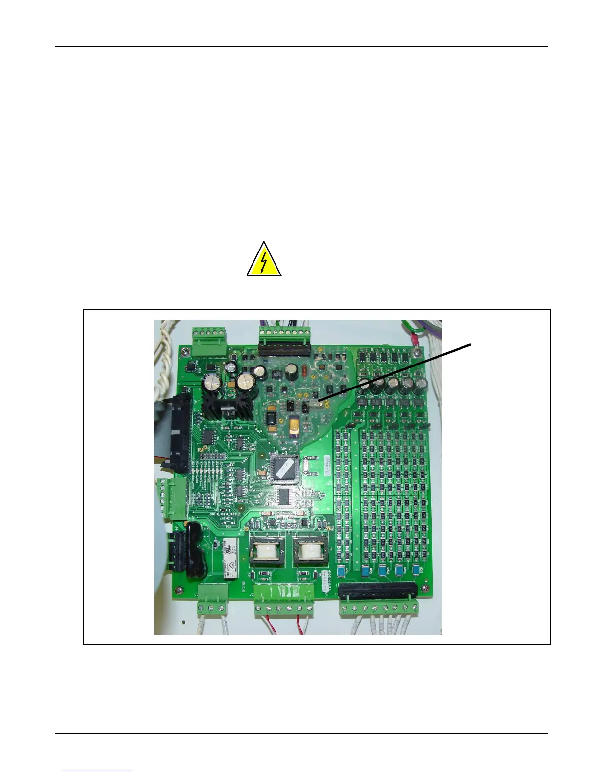
3. See Figure 4-4. Carefully adjust R40 on the universal
regulator controller board until the desired current is measured on the
meter.
WARNING: Dangerous voltages are present on the URC PCB.
It is strongly recommended that a nonconductive screwdriver be
used during calibration to protect personnel as we as the card
from accidentally shorting.
Figure 4-4 R40 (URC Board)
Output Current Adjustment
(cont.)
 Loading...