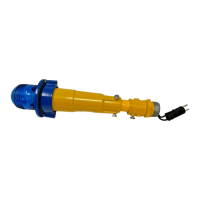
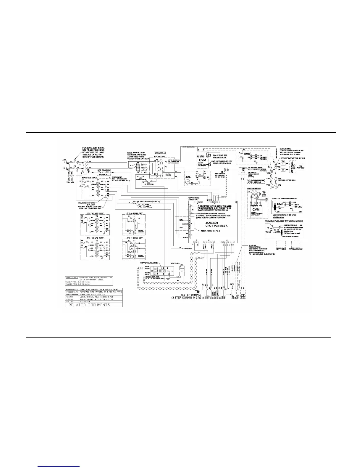
Home
ADB
Controller
Signature Series
ADB Signature Series User Manual
5
of 1
of 1 rating
79 pages
Give review
Manual
Specs
To Next Page
To Next Page
To Previous Page
To Previous Page
Loading...
Ferroresonant L-828/L-
829 CCR
Wiring Schematics
2009 ADB Airfield Solutions, Incorporated
96A0288T
Page
8-2
All rights reserved
Issued 9/04
NOTE: See Fig 8
-
3
for 50/70 kW Wiring
Figure 8
-
1 L828/L829 Ferro
4
-
30kW, 6.6A
–
20A Internal Wiring Schematic (Part
1 of 2)
74
76
Table of Contents
Table of Contents
4
Section 1 Safety
9
Introduction
9
Safety Symbols
9
Qualified Personnel
10
Intended Use
11
Installation
11
Operation
12
Action in the Event of a System or Component Malfunction
13
Maintenance and Repair
13
Figure 2-1 L-828 CCR (4 -30Kw/6.6 A)
14
Section 2 Description
14
Introduction
14
Figure 2-2 L-829 CCR with ACE2
15
Figure 2-3 SGRS Powerpack with ACE or ACE2
16
Figure 2-4 Universal Regulator Controller (URC)
17
Universal Regulator Controller
17
L-829 Advanced Control Equipment (ACE™ or ACE2)
18
SGRS Powerpack
16
L-828/L-829 CCR Monitoring Options
19
Optional Insulation Resistance Monitoring System
19
Optional Scanning Monitor Interface
19
Optional Scanning Monitor Ready
19
Optional Series Cutout Type SCO
19
Theory of Operation
20
Power Circuit
20
Output Measurement
20
Universal Regulator Controller
20
Figure 2-5 L-828 CCR Power Circuit Block Diagram
20
Ferroresonant L-828 Ccrs (4-70 Kw 6.6 A/20 A): Required Equipment
22
Table 2-1 Required Equipment Supplied
22
Table 2-2 Required Equipment Not Supplied
22
Input Power Breaker Sizing
23
Rating
23
Table 2-3 Recommended Input Wiring Rating
23
Table 2-4 CCR Input Current
23
Specifications
24
Ratings
24
Style
24
Power Factor
24
Efficiency
24
Table 2-5 Class
24
Table 2-6 Style
24
Table 2-7 Power Factor
24
Table 2-8 Efficiency
24
Reactive Loading
25
Resistive Loading
25
Regulation
25
Table 2-9 Output Current
25
Environmental Operating Conditions
26
Protection Devices
26
Input Voltage
27
Built-In True RMS-Reading Ammeter
27
Input Wire Size
27
Rating and Input Voltage
27
Temperature Rise
27
Table 2-10 Rating and Input Voltage
27
Approximate Weight - Pounds (Kg)
28
CCR Dimensions - Inches (Centimeters)
28
Table 2-11 L-828/L-829 CCR Weight
28
Table 2-12 L-828/L-829 CCR Dimensions
28
Section 3 Installation
30
Introduction
30
Unpacking
30
Installation
30
Wiring Connections and Startup
30
Figure 3-1 Wiring on Right Side of CCR
31
Table 3-1 Remote 120 Vac Control Connections (3-Step/6.6 A)
32
Table 3-3 Remote 120 Vac Control Connections (5-Step/20 A)
33
Figure 3-2 Location of Bolts for Stacking Ccrs
35
Stacking Ccr's (Optional)
35
Figure 3-3 Stacking Bolt
36
Figure 3-4 Powerpack Installation in SGRS
37
SGRS Style Powerpacks (Optional)
37
Section 4 Operation
38
Introduction
38
CCR Control Procedures
38
Local Control
38
Figure 4-1 Switch (3-Step/5-Step)
38
Remote Control
39
Table 4-1 Output Current from Rotary Switch (3-Step/6.6A)
39
Table 4-4 Remote Control
39
CCR Door Interlock (Optional)
40
CCR Shutdown Procedure
40
Figure 4-2 SGRS Powerpack with ACE or ACE2
40
CCR Adjustment Procedures
41
Output Current Adjustment
41
Figure 4-3 Output Current Clamp
41
Output Current Adjustment (Cont.)
42
Figure 4-4 R40 (URC Board)
42
Overcurrent Adjustment
43
S1 Cutout Type SCO Working Positions
43
Figure 4-5 Handle Orientations
43
Figure 4-6 S1 Cutout Operation Position
43
Figure 4-7 S1 Cutout Maintenance Position
44
Figure 4-8 S1 Cutout Test and Measure Position
44
Digital Power Meter Calibration
45
Figure 4-9 Meter Display
45
Figure 4-10 Function Buttons
45
Figure 4-11 Calibration Menu
47
Figure 4-12 Irms High Step Calibration
48
Figure 4-13 Irms Low Step Calibration
48
Figure 4-14 Vrms Calibration
48
Figure 4-15 Vrms High Step Loaded
49
Figure 4-16 Save Vrms Calibration
49
Section 5 Maintenance
50
Introduction
50
Maintenance Schedule
51
Table 5-1 L-828/L-829 CCR (4-70 Kw/6.6 A/20 A) Maintenance
51
Open-Circuit Test
52
Short-Circuit Test
52
Section 6 Troubleshooting
54
Introduction
54
Preliminary Troubleshooting
55
Troubleshooting Fuses
56
L-828/L-829 Input Power Fuses F1 and F2
56
L-828 / L-829 Step-Down T4 Transformer Fuses F3 and F4
56
Table 6-1 Input Power Fuses, F1 and F2, Per CCR Input Voltage and CCR Kw
56
Table 6-2 Transformer T3 Fuses F3 and F4 Ratings
56
Table 6-3 Fuses F5 and F6 Ratings
57
L-829 General Troubleshooting Procedures
62
Feedback Wiring Modification Procedure
62
Section 7 Parts
63
Introduction
63
Using the Illustrated Parts List
63
Figure 7-1 L-828/L-829 Part Ordering Code
64
Table 7-1 L-828/L-829 CCR (4-70 Kw/6.6A & 20 A) Part Numbers
64
SGRS Powerpack CCR (4-70 Kw/6.6 A) Part Ordering Code
65
Figure 7-2 SGRS Powerpack Part Ordering Code
65
Table 7-2 SGRS Powerpack (4-70 Kw/6.6 A) Part Numbers
65
L-828/L-829 CCR General Assembly
66
Figure 7-3 CCF-828/L-829 CCR Component Mounting Plate Parts (Part 1 of 3)
70
L-828/L-829 CCR Optional Parts
73
Universal Regulator Controller Parts List
73
Recommended Spare Parts
73
Introduction
74
Wiring Schematics
74
5
Based on 1 rating
Ask a question
Give review
Questions and Answers:
Need help?
Do you have a question about the ADB Signature Series and is the answer not in the manual?
Ask a question
ADB Signature Series Specifications
General
Brand
ADB
Model
Signature Series
Category
Controller
Language
English