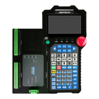
User Manual of TV5600-B01 Series Dispensing Control System
System R axis
※Note: The DRIVER POWER terminal is the drive motor power supply, and only one set of VDC
and GND needs to be connected.
3.02 Four-axis closed-loop feedback signal input wiring definition
EN-0 terminal pin description:
Negative pole ofclosed loop feedback power
supply
Positive pole ofclosed loop feedback power
supply
A-phase negative pole ofZ-axis closed loop
feedback signal
A-phase positive pole ofZ-axis closed loop
feedback signal
B-phase negative pole ofZ-axis closed loop
feedback signal
B-phase positive pole ofZ-axis closed loop
feedback signal

 Loading...