vii AIMB-286 User Manual
Contents
Chapter 1 General Information ............................1
1.1 Introduction ............................................................................................... 2
1.2 Features.................................................................................................... 2
1.3 Specifications............................................................................................ 2
1.3.1 System.......................................................................................... 2
1.3.2 Memory......................................................................................... 2
1.3.3 Input/Output .................................................................................. 2
1.3.4 Graphics........................................................................................ 3
1.3.5 Ethernet LAN ................................................................................ 3
1.3.6 Industrial features ......................................................................... 3
1.3.7 Mechanical and environmental specifications............................... 3
1.4 Jumpers and Connectors.......................................................................... 3
Table 1.1: Connector and Header List......................................... 4
Table 1.2: Jumper List................................................................. 5
1.5 Board layout: Jumper and Connector Locations....................................... 5
Figure 1.1 Jumper and Connector Location (Top Side)............... 5
Figure 1.2 Jumper and Connector Location (Bottom Side) ......... 6
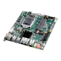
1.6 AIMB-286 Board Diagram......................................................................... 7
Figure 1.3 AIMB-286 Board Diagram .......................................... 7
1.7 Safety Precautions.................................................................................... 7
1.8 Jumper Settings ........................................................................................ 8
1.8.1 How to Set Jumpers...................................................................... 8
1.8.2 CMOS Clear (JCMOS1)................................................................ 8
Table 1.3: CMOS1....................................................................... 8
1.8.3 Power Switch/HDD LED/SMBUS/Speaker Pin Header (JFP1) .... 9
Table 1.4: Power Switch/HDD LED/SMBUS/Speaker Pin Header
(JFP1)......................................................................... 9
1.8.4 Power LED and Keyboard Lock Pin Header (JFP2) ..................... 9
Table 1.5: Power LED and Keyboard Lock Pin Header (JFP2)... 9
1.8.5 Watchdog Timer Output and OBS Beep (JWDT1+JOBS1).......... 9
Table 1.6: Watchdog Timer Output and OBS Beep
(JWDT1+JOBS1)........................................................ 9
1.8.6 ATX/AT Mode Selection (PSON1).............................................. 10
Table 1.7: ATX/AT Mode Selection (PSON1)............................ 10
1.8.7 LVDS/eDP Panel Voltage Selection (JLVDS1)........................... 10
Table 1.8: LVDS/eDP Panel Voltage Selection (JLVDS1) ........ 10
1.8.8 COM1 RI# Pin RI#/5V/12V Select (JSETCOM1_V1) ................. 11
Table 1.9: COM1 RI# Pin RI#/5V/12V Select (JSETCOM1_V1)11
1.8.9 JCASEOP_SW1: Case open selection pin header..................... 11
Table 1.10:JCASEOP_SW1: Case open selection pin header .. 11
1.8.10 JLVDS_VCON1: LVDS VESA, JEIDA format selection pin header
11
Table 1.11:JLVDS_VCON1: LVDS VESA, JEIDA format selection
pin header................................................................. 11
1.9 System Memory ...................................................................................... 12
1.10 Memory Installation Procedures.............................................................. 12
1.11 Cache Memory........................................................................................ 12
1.12 Processor Installation.............................................................................. 12
Chapter 2 Connecting Peripherals ....................13
2.1 Introduction ............................................................................................. 14
2.2 LAN + USB Ports (LAN1/2/3, USB12, USB34) ....................................... 14
Table 2.1: LAN LED Indicator.................................................... 14