AEQ Audio Over IP
Routing System
21
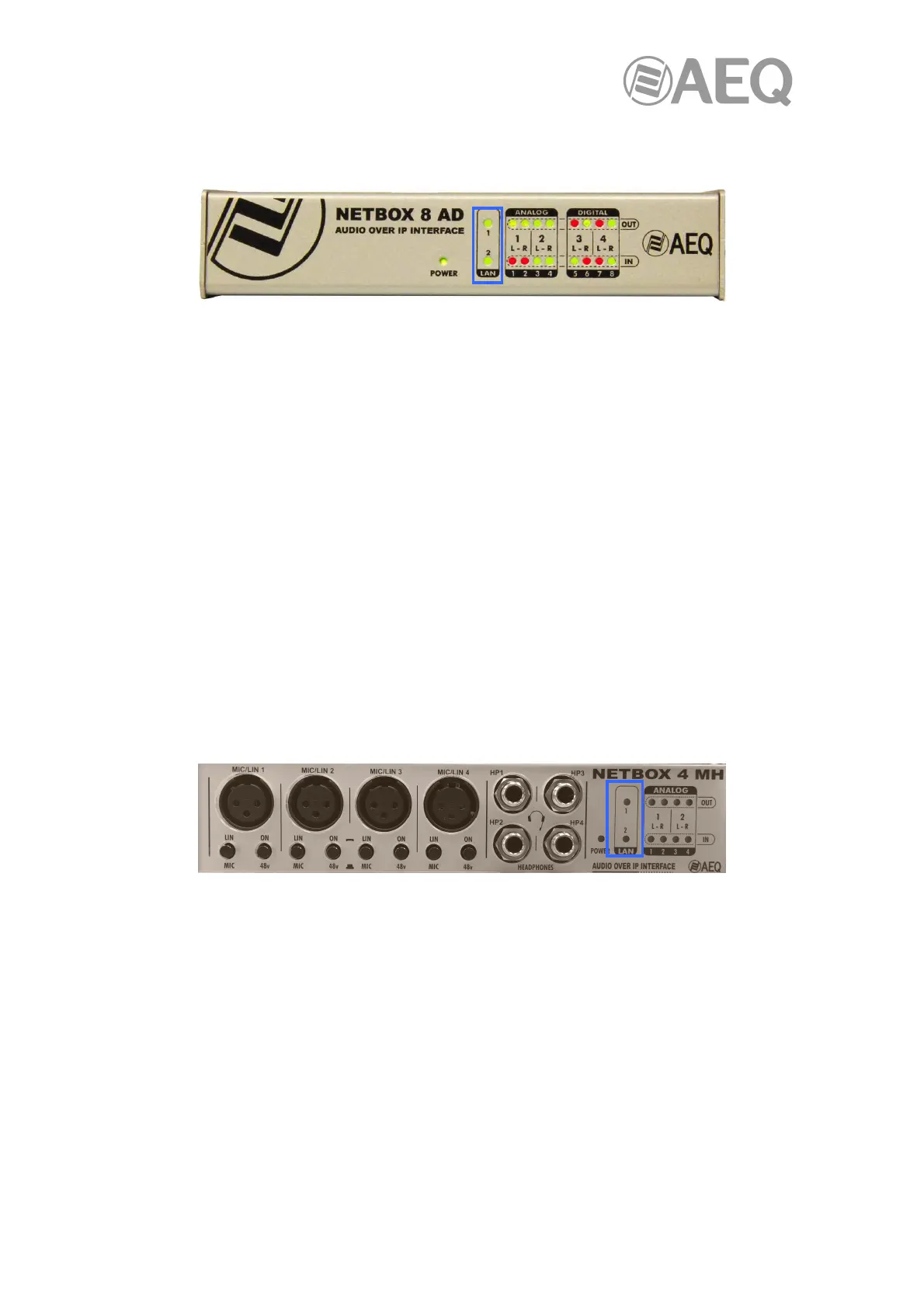
2.5. NETBOX 8 AD interface description.
2.5.1. Front panel description.
NETBOX 8 AD includes 2 connectors, LAN 1 and LAN 2, placed on the back panel of the unit,
each one with its respective physical link signaling LEDs.
On front panel, there are indicators related to the unit status, communications and audio levels.
The ones that are interesting regarding AoIP connection are:
- LAN LEDs: indicate the status of the audio local area network: LAN 1 (main interface)
and LAN 2 (secondary interface).
Status:
• Off: no local network connection.
• Blinking green: link is established at data level.
If the unit is wired to a dedicated audio network using a switch, only LAN 1 should be blinking. If
the wiring is connected in "Daisy Chain" mode, without switch, or there is a redundant network,
both LEDs be blinking.
IMPORTANT NOTE: When there is a redundant network, primary and secondary interfaces
must be connected to separated networks.
2.6. NETBOX 4 MH interface description.
2.6.1. Front panel description.
NETBOX 4 MH includes 2 connectors, LAN 1 and LAN 2, placed on the back panel of the unit,
each one with its respective physical link signaling LEDs.
On front panel, there are indicators related to the unit status, communications and audio levels.
The ones that are interesting regarding AoIP connection are:
- LAN LEDs: indicate the status of the audio local area network: LAN 1 (main interface)
and LAN 2 (secondary interface).
Status:
• Off: no local network connection.
• Blinking green: link is established at data level.
LAN 1 must always be wired, while LAN 2 is only wired when the system is installed in "switch"
mode or when it is configured to separate control and AoIP networks.
IMPORTANT NOTE: NETBOX 4 MH does not allow redundant operation.