10
IT
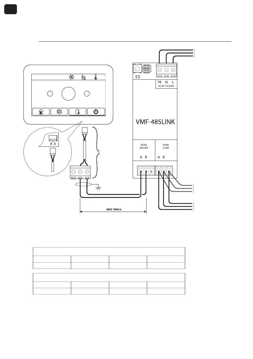
4. COLLEGAMENTO CON HMI / BHP
4.1. FASE 1 - Collegamenti elettrici
GND GND
2020-02-20 08:52 0.0°C 0.0°C
+
-
25°C
Nodo precedente
rete VMF
Nodo successivo
rete VMF
Vin: 230 Vac
50/60 Hz
Imax: 0.15 A
IC-2P
(Accessorio)
Retro del
pannello
NOTE:
1. per le unità HMI o BHP è necessario il connettore accessorio IC-2P disponibile come accessorio;
2. prima di procede oltre assicurarsi che i dipswitches SW1 siano correttamente configurati:
SW1 (HMI o BHP con gestione integrata dell’acqua sanitaria)
DIP 1 DIP 2 DIP 3 DIP 4
ON OFF OFF ON
SW1 (HMI o BHP senza gestione integrata dell’acqua sanitaria)
DIP 1 DIP 2 DIP 3 DIP 4
ON OFF OFF OFF
Pannello comandi HMI / BHP