58
ES
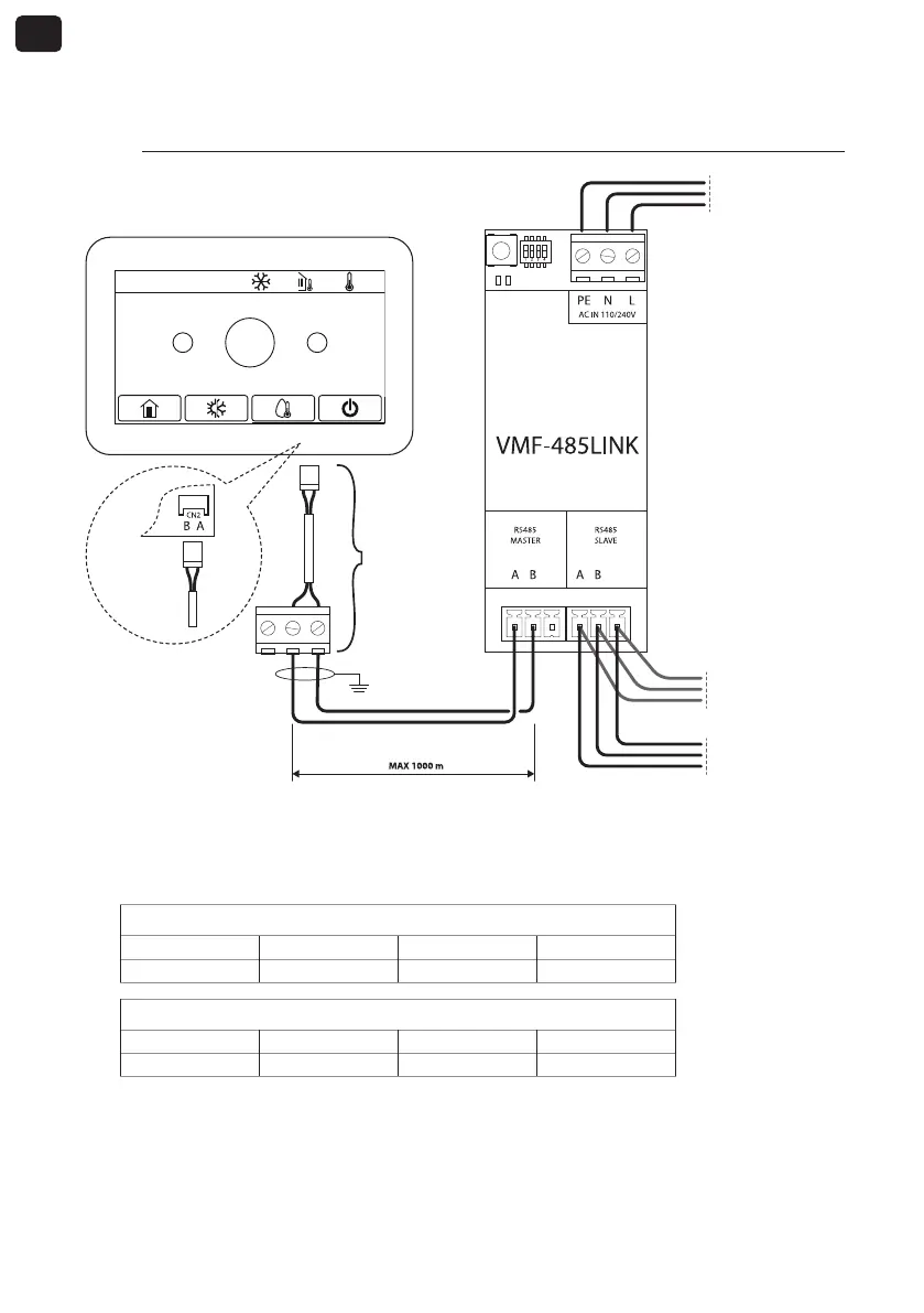
4. CONEXIÓN CON HMI / BHP
4.1. FASE 1 - Conexiones eléctricas
GND GND
2020-02-20 08:52 0.0°C 0.0°C
+
-
25°C
Nodo anterior
red VMF
Nodo siguiente
red VMF
Vin: 230 Vac
50/60 Hz
Imáx: 0.15 A
IC-2P
(Accesorio)
Parte poste-
rior del
panel
NOTAS:
1. para las unidades HMI o BHP se necesita el conector IC-2P disponible como accesorio;
2. antes de proceder, asegurarse también de que los dipswitches SW1 estén configurados correctamente:
SW1 (HMI o BHP con gestión integrada del agua sanitaria)
DIP 1 DIP 2 DIP 3 DIP 4
ON OFF OFF ON
SW1 (HMI o BHP sin gestión integrada del agua sanitaria)
DIP 1 DIP 2 DIP 3 DIP 4
ON OFF OFF OFF
Tablero de mando HMI / BHP