5
IT
2. INTERFACCIA UTENTE
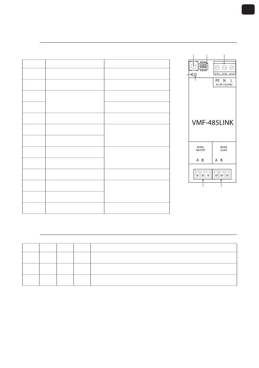
2.1. Layout interfaccia seriale VMF-485 LINK
GND GND
T1 SW1 M1
M2 M3
I/O Funzione Caratteristica
T1 Tasto avvio riconoscimento ---
SW1 Dipswitches di settaggio ---
DL5
Led di segnalazione
led bianco
DL6 led rosso
M1(PE) Collegamento messa a terra ---
M1 (N) Alimentazione (NEUTRO)
Vin: 230 Vac
50/60 Hz
Imax: 0.15 A
M1 (L) Alimentazione (LINEA)
M2 (A) Seriale MASTER (T+)
V max −9 [V] ÷ +14 [V]
M2 (B) Seriale MASTER (T-)
M2 (GND) Seriale MASTER (GND) ---
M3 (A) Seriale SLAVE (T+)
V max −9 [V] ÷ +14 [V]
M3 (B) Seriale SLAVE (T-)
M3 (GND) Seriale SLAVE (GND) ---
2.2. Settaggio dipswitches SW1
DIP 1 DIP 2 DIP 3 DIP 4 Unità
OFF OFF OFF --- Fancoil FCWI
ON OFF OFF ON Pompa di calore HMI o BHP con gestione integrata dell’acqua sanitaria
ON OFF OFF OFF Pompa di calore HMI o BHP senza gestione integrata dell’acqua sanitaria
DL6
DL5