17
EN
2. USER INTERFACE
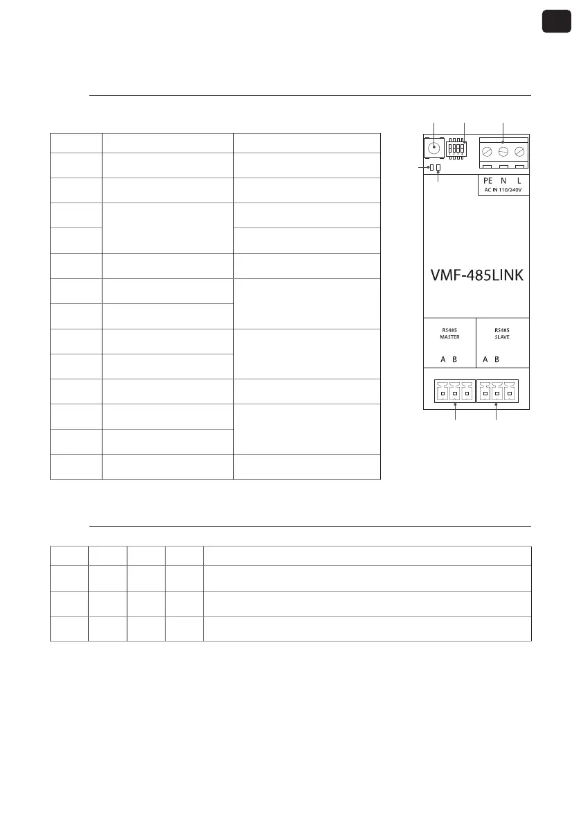
2.1. Layout of serial interface VMF-485 LINK
GND GND
T1 SW1 M1
M2 M3
I/O Function Characteristic
T1 Start recognition button ---
SW1 Settings Dip-switches ---
DL5
Signalling LED
WHITE LED
DL6 RED LED
M1(PE) Earth connection ---
M1 (N) Power supply (NEUTRAL)
Vin: 230 Vac
50/60 Hz
Imax: 0.15 A
M1 (L) Power supply (LINE)
M2 (A) MASTER Serial (T+)
V max −9 [V] - +14 [V]
M2 (B) MASTER Serial (T-)
M2 (GND) MASTER Serial (GND) ---
M3 (A) SLAVE Serial (T+)
V max −9 [V] - +14 [V]
M3 (B) SLAVE Serial (T-)
M3 (GND) SLAVE Serial (GND) ---
2.2. SW1 dip-switches settings
DIP 1 DIP 2 DIP 3 DIP 4 Unit
OFF OFF OFF --- FCWI Fancoil
ON OFF OFF ON
HMI or BHP heat pump with integrated management of the Domestic Hot
Water
ON OFF OFF OFF
HMI or BHP heat pump without integrated management of the Domestic Hot
Water
DL6
DL5