29
FR
2. INTERFACE UTILISATEUR
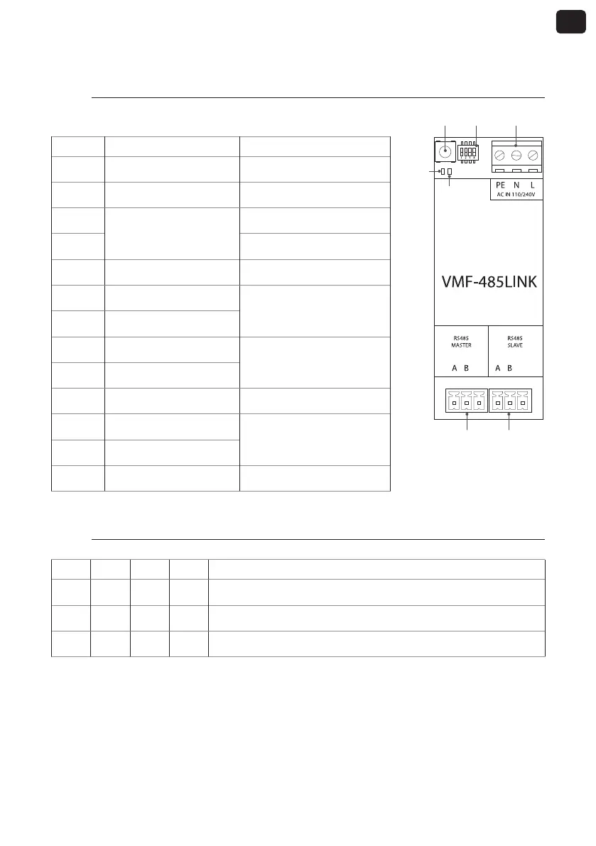
2.1. Disposition de l'interface série VMF-485 LINK
GND GND
T1 SW1 M1
M2 M3
E/S Fonction Caractéristique
T1
Touche de démarrage de
reconnaissance
---
SW1
Commutateurs DIP de
réglage
---
DL5
Voyant de signalisation
Voyant blanc
DL6 Voyant rouge
M1(PE)
Raccordement de mise à la
terre
---
M1 (N) Alimentation (NEUTRE)
Vin : 230 Vca
50/60 Hz
Imax : 0.15 A
M1 (L) Alimentation (LIGNE)
M2 (A) Série MASTER (T+)
V max −9 [V] ÷ +14 [V]
M2 (B) Série MASTER (T-)
M2 (GND) Série MASTER (GND) ---
M3 (A) Série SLAVE (T+)
V max −9 [V] ÷ +14 [V]
M3 (B) Série SLAVE (T-)
M3 (GND) Série SLAVE (GND) ---
2.2. Réglage des commutateurs DIP SW1
DIP 1 DIP 2 DIP 3 DIP 4 Unité
OFF OFF OFF --- Ventilo-convecteur FCWI
ON OFF OFF ON Pompe à chaleur HMI ou BHP avec gestion intégrée de l'eau sanitaire
ON OFF OFF OFF Pompe à chaleur HMI ou BHP sans gestion intégrée de l'eau sanitaire
DL6
DL5