4349B
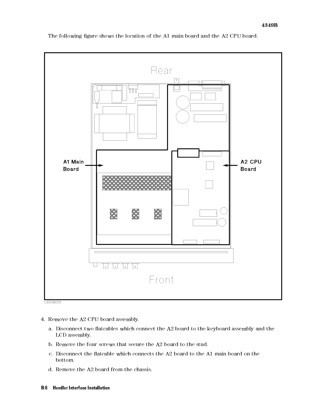
The
following gure
shows the
location
of
the
A1
main
board
and
the
A2
CPU
board.
4. Remove the A2 CPU board assembly
.
a. Disconnect two atcables which connect the A2 board to the keyboard assembly
and the
LCD assembly.
b. Remove the four screws that secure the A2 board to the stud.
c. Disconnect the atcable which connects the A2 board to the A1 main board on the
bottom.
d. Remove the A2 board from the chassis.
B-6 Handler Interface Installation

 Loading...


