Chapter 6: Replacing Assemblies
To remove and replace the interface and GPIB board
6–24
To remove and replace the interface and GPIB board
Use this procedure to remove and replace the interface and GPIB board, A21. When necessary,
refer to other removal procedures.
1 Disconnect the power cable and remove the cover.
2 Remove the keyboard cable (W12) and the acquisition board cable (W3) from the
interface and GPIB board.
3 Remove the Torx T10 screw that secures the interface and GPIB board to the rear of
the chassis.
4 Pull the board up to disengage it from the motherboard, then lift up and out of the
chassis.
5 To replace the board, reverse the removal procedure.
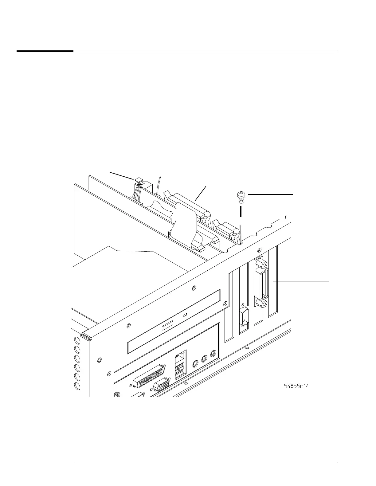
Figure 6-23
Removing the Interface and GPIB Board
W3 Cable
T10 Torx Screw
Interface & GPIB
Board(A21)
W12 Cable
 Loading...


