Chapter 2: Preparing for Use
To verify basic oscilloscope operation
2–18
To verify basic oscilloscope operation
1 Connect an oscilloscope probe to channel 1.
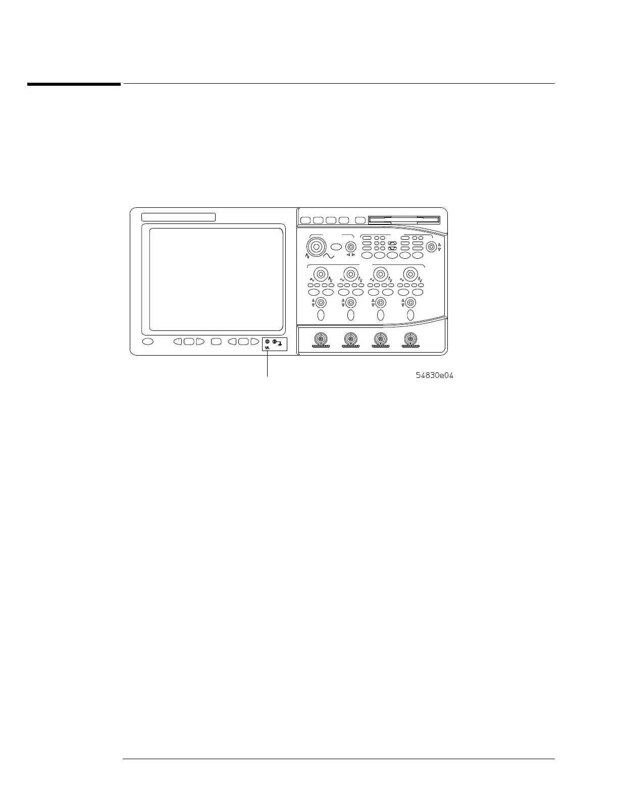
2 Attach the probe to the calibration output on the front panel of the oscilloscope.
Use a probe grabber tip so you do not need to hold the probe. The calibration output is marked
with a square wave symbol.
Figure 2-15
Verifying Basic Oscilloscope Operation for 54830 Series Oscilloscopes.
3 Press the Default Setup key on the front panel.
The display will pause momentarily while the oscilloscope is configured to its default settings.
4 Press the Autoscale key on the front panel.
The display will pause momentarily while the oscilloscope adjusts the sweep speed and vertical
scale. You should then see a square wave with peak-to-peak amplitude of approximately 5
divisions and a period of almost 7 divisions. If you do not see the waveform, ensure your power
source is adequate, the oscilloscope is properly powered-on, and the probe is connected securely
to the front-panel channel input BNC and to the probe calibration output.
5
Move the mouse around the mouse surface and verify that the on screen mouse pointer
follows moves with the mouse movement.
Calibration
Output
 Loading...


