3 Installing Intuvo 9000 GC Column
To Install a Column Guard or Jumper Chip
7000/7010 Series TQ GC/MS Operating Manual 59
3 Wait until the GC reaches the ready state indicating the components are
cooled below 40 °C and the instrument is vented before continuing the steps
in this procedure.
4 If you are using hydrogen or other flammable gas as a carrier gas or for the
JetClean system, close the manual gas supply valve to the instrument before
turning off the MS power.
5 If installed, remove the ALS injector from the inlet.
6 Remove the inlet cover. (See Figure 11.)
7 Open the GC front door.
8 Open the bus door and remove it by lifting the door vertically off its hinge
pins.
9 Pull the compression bolt access plate out to allow the torque driver to
access the Guard chip compression bolt. (See Figure 12 on page 60.)
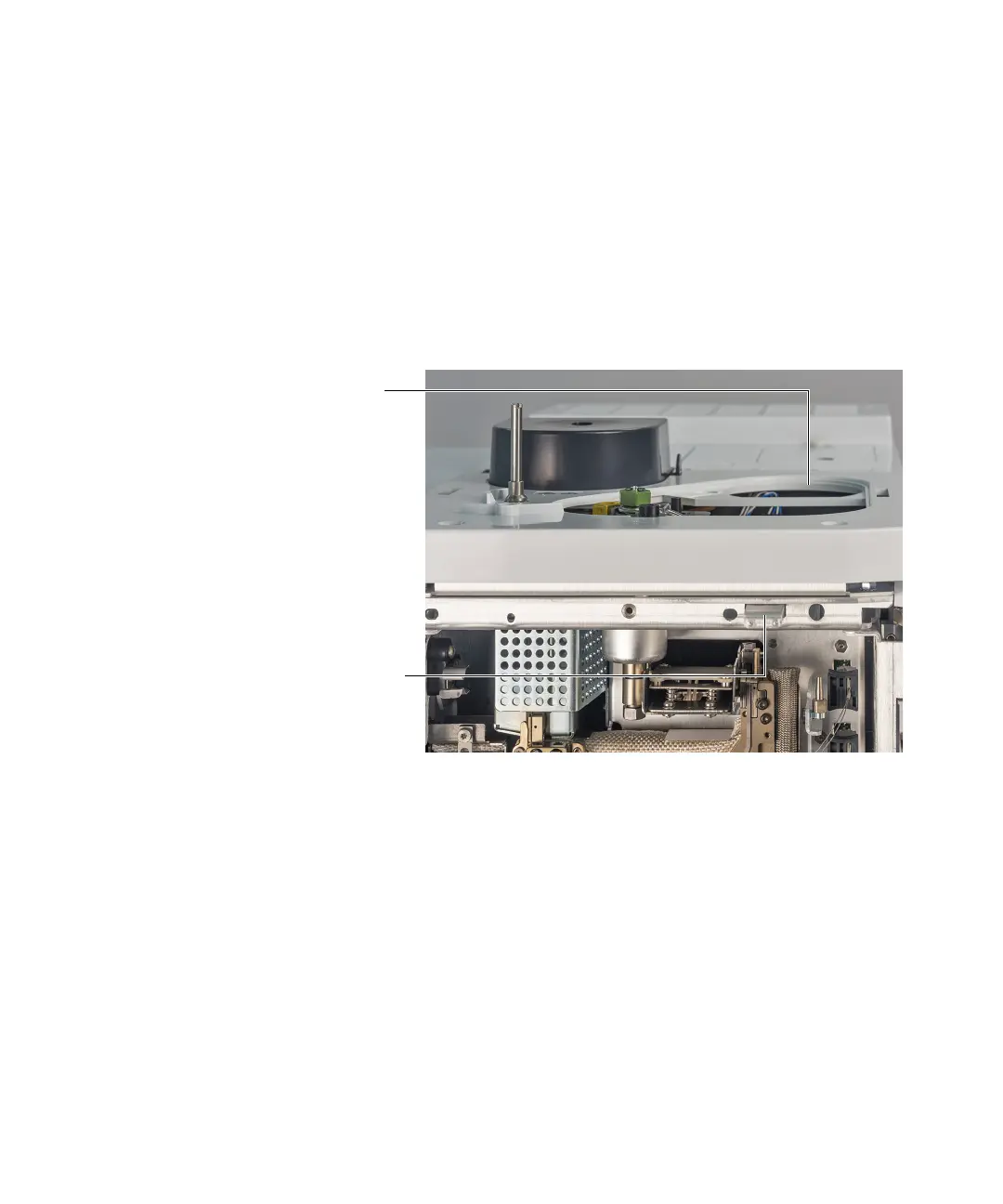
Figure 11. GC inlet cover and compression bolt access plate
GC inlet cover
removed
Compression bolt
access plate
 Loading...


