70
Using the 81110A/81104A
T
TT
The
he he
he M
MM
Mo
oo
ode
dede
de/
//
/T
TT
Tr
rr
ri
ii
igg
gggg
gge
ee
er
r r
r S
SS
Sc
cc
cr
rr
ree
eeee
een
nn
n
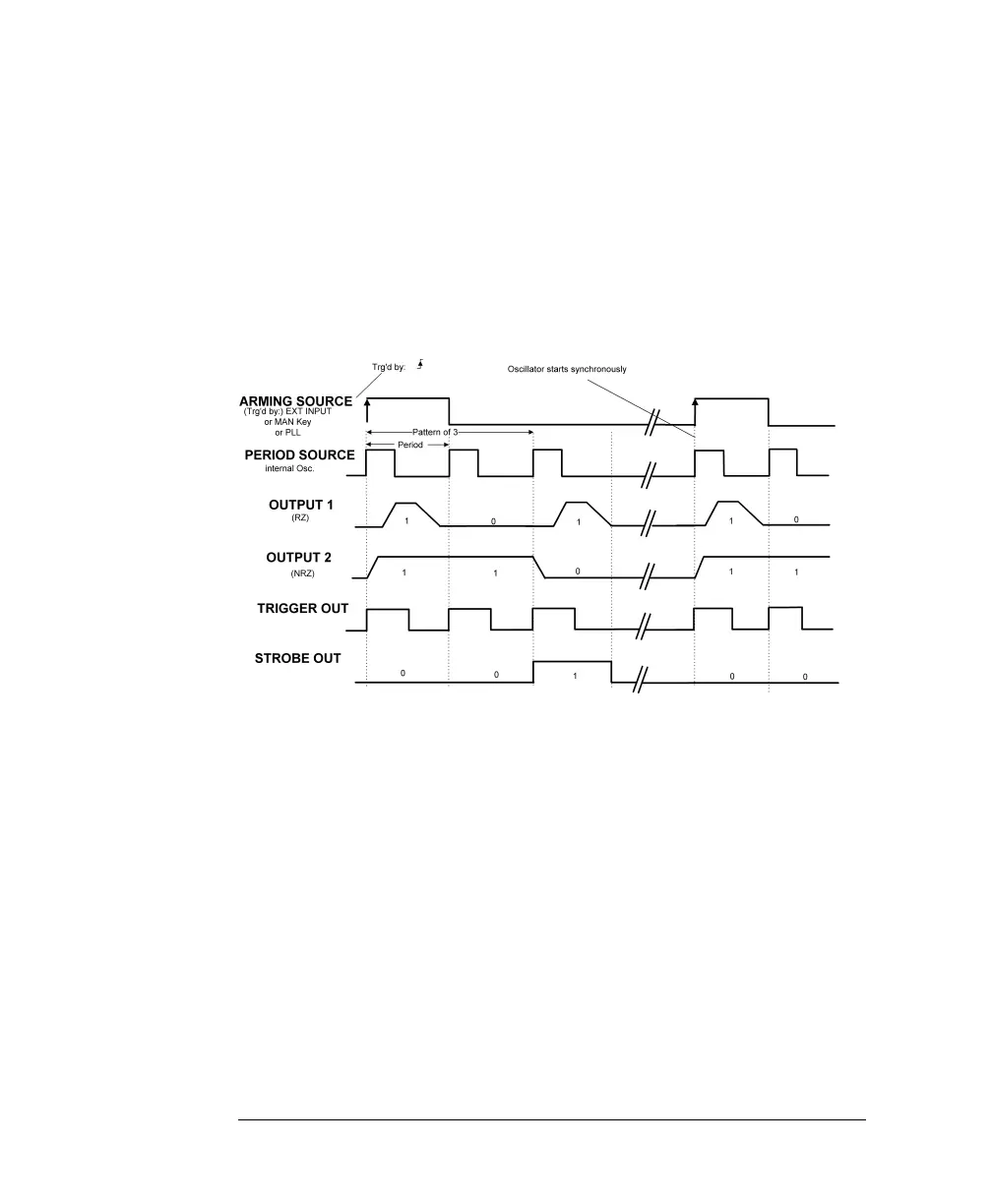
Triggered Pattern Mode
The following figures show typical timings for trigger mode TRIGGERED
and pulse mode PATTERN.
For the first example, the synchronously triggerable internal oscillator is
used to source the period. The patterns are triggered by the rising edge of
the arming source.
C
CC
Ch
hh
ha
aa
ar
rr
ra
aa
ac
cc
ct
tt
te
ee
er
rr
ri
ii
is
ss
st
tt
ti
ii
ic
cc
cs
ss
s
A pattern of pulses is triggered by an active edge from the selected
arming source.
MAN K
EY
on front panel, triggered by press, release or both.
EXT INPUT (External signal) triggered by rising, falling or both
edges.
PLL (Internally triggered patterns), select the triggering period.
You can select between RZ and NRZ data pulses for each output.
On the Pattern screen you can set the pattern length in the range of 2
16384 and program the data values for each OUTPUT.
TRIGGER OUT marks each pulse period.
STROBE OUT is bit-programmable on the Pattern screen (NRZ
format only).