20
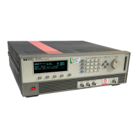
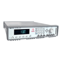
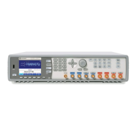
Introducing the 81110A/81104A Pulse and Pattern Generators
O
OO
Op
pp
pe
ee
er
rr
ra
aa
at
tt
ti
ii
in
nn
ng
g g
g t
tt
th
hh
he
e e
e 81110
8111081110
81110A
AA
A/
//
/81104
8110481104
81104A
AA
A
Operating the 81110A/81104A
This section guides you through the first steps when operating the
81110A/81104A via the user interface.
N
NN
NO
OO
OTE
TETE
TE For information on operating the 81110A/81104A via remote control,
please refer to the Reference Guide, part number 81110-91021.
Switching On the Instrument
After switching on the instrument the display indicates that the
instrument selftest is running. This can take several seconds to complete.
If the selftest fails, you see a flashing E at the bottom of the screen. Press
the HELP key to see a list of the selftest error messages. Use the knob or
the cursor keys to scroll through the list if necessary.
To return to normal operation press HELP again. Note that the selftest
error messages are removed from the error queue after this.