10-38 Chapter 10
Service Key Menus and Error Messages
Service Key Menus
Node 27 VCXO Tune (40 MHz VCXO tuning voltage)
Perform step A12 and then press
.
This node displays the voltage used to fine tune the A12 reference VCXO to 40 MHz. You
should see a flat line at some voltage level (the actual voltage level varies from instrument
to instrument). Anything other than a flat line indicates that the VCXO is tuning to
different frequencies. Refer to “Frequency Accuracy Adjustment” on page 3-43.
Node 28 A12 Gnd 2 (Ground reference)
A14 Fractional-N (Digital) To observe the A14 analog bus nodes perform step A14,
below. Then follow the node-specific instructions.
Step A14: Press
.
Node 29 FN VCO Tun (A14 FN VCO tuning voltage)
Perform step A14 and then press
.
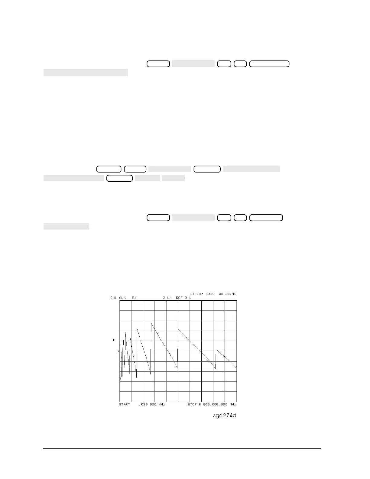
Observe the A14 FN VCO tuning voltage. If the A13 and A14 assemblies are functioning
correctly and the VCO is phase locked, the trace should look like Figure 10-16. Any other
waveform indicates that the FN VCO is not phase locked. The vertical lines in the trace
indicate the band crossings. (The counter can also be enabled to count the VCO frequency
in CW mode.)
Figure 10-16 Analog Bus Node 29
27 x1 Marker Fctn
→
Preset Meas
System
Format
29 x1 Scale Ref

 Loading...


