Dual Channel Operations
When signals are combined, the DC Offset values are not added together. Only the DC Offset from the receiving chan-
nel is used in the combined output. The figure below shows 50 a mV DC Offset added to Channel 1. The 50 mV offset
added to Channel 2 is ignored.
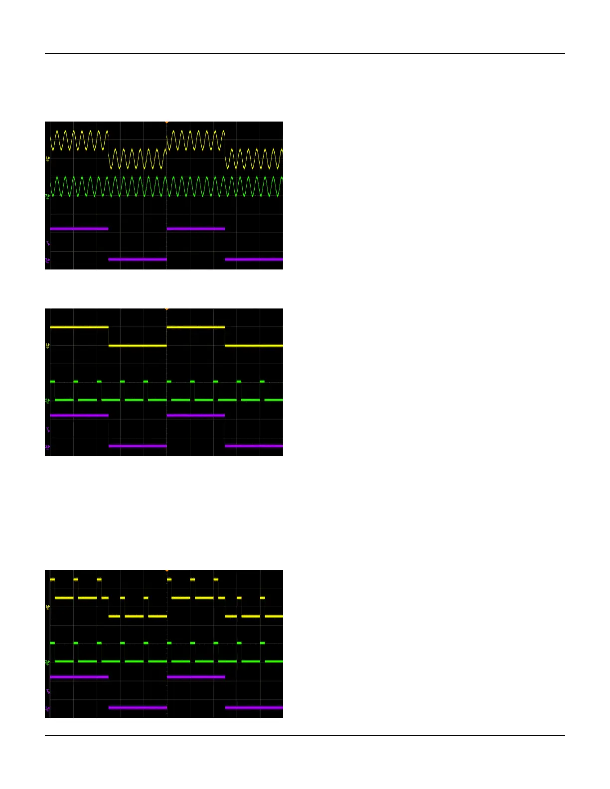
Logic signal amplitudes are added in the same way as any other signal. They are not OR’d together. For example, con-
sider the signals below.
When these are combined, the amplitudes are added, as shown below. Note that the combined signal has three voltage
levels: 150 mV, 50 mV and -50 mV. This is a result of the following combinations:
l CH1 +50 mV + 50 mV DC Offset, plus CH2 +50 mV signal = +150 mV.
l CH1 -50 mV + 50 mV DC Offset, plus CH2 +50 mV signal = + 50 mV.
l CH1 -50 mV + 50 mV DC Offset, plus CH2 -50 mV signal = -50 mV.
l CH1 +50 mV + 50 mV DC Offset, plus CH2 -50 mV signal = +50 mV.
Agilent 33500 Series Operating and Service Guide 109

 Loading...


