Troubleshooting
l If there is no activity on the line even after the LED lights up, then most likely the main board is the cause of the
failure.
l If there is activity on the line, then the processor board is the most likely cause of the failure.
Main Board LED Does not Light up after Boot
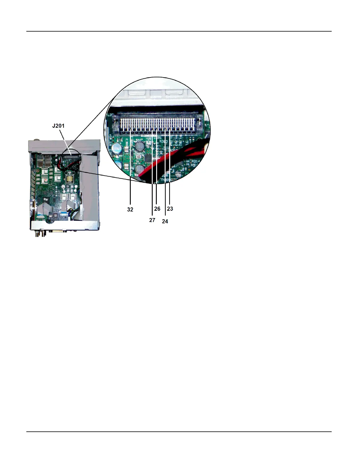
This indicates that the processor was unable to program the FPGA. Most likely there is a communications failure from
the processor board to the main board. Probe the following serial data lines at power up with an oscilloscope:
l J201, pin 23
l J201, pin 24
l J201, pin 26
l J201, pin 32
If all of the above SPI lines show activity during FPGA programming, then the main board is the most likely cause of the
failure. Otherwise, the processor board is the most likely cause.
10 MHz Out
If the power supplies are functional and self-test passes, check the 10 MHz output at the rear panel. This output is
present whenever the instrument has powered on and the processor and main board are operational. If the 10 MHz is
present, but the display is not working, suspect the front panel board or display assembly.
414 Agilent 33500 Series Operating and Service Guide

 Loading...


