103
Chapter 4 Features and Functions
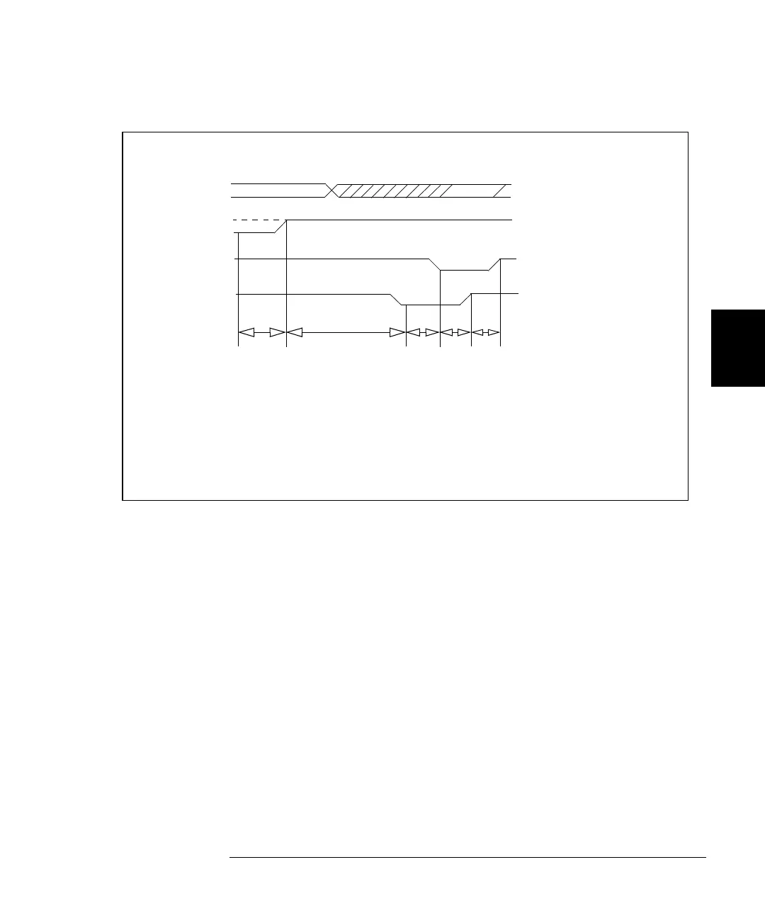
Digital I/O Operation
4
4
DATA LINES
I/O DIRECTION
Read Operation
DATA VALID
LATCHED
PFLG LINE
PCTL LINE
t1
100 µs
t2
45 µs
t3
50 µs
t4
40 µs
t5
35 µs
t1 = Time from output
disable to I/O line
high (100
µs
minimum)
t2 = Time from I/O line
high to check for
PFLG low
t3 = Time from PFLG low
to check for PCTL
low (50
µs
minimum)
t4 = Time from PCTL low
to check PFLG
high (40
µs
minimum)
t5 = Time from PFLG
high to PCTL high
and data latched
(35
µs
minimum)
(45
µs
minimum)
As with the Write operation, the 3499A/B/C begins by testing PFLG for a
low state, indicating that the data is valid. When PFLG is low, the
3499A/B/C sets PCTL low and waits for PFLG to go high. The 3499A/B/C
will set PCTL high to indicate that it has completed the data read operation.
Data on the data bus must remain valid until after the 3499A/B/C sets
PCTL high.
 Loading...