102
Chapter 4 Features and Functions
Digital I/O Operation
4
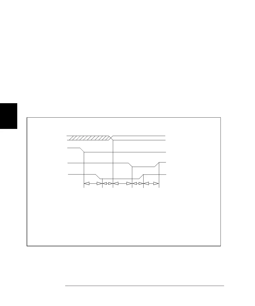
Full Handshake Mode #5
Handshake Mode #5 provides a complete two wire handshake with a
data direction line. During write operations, the PCTL line indicates that
output data is valid; during read operations, it indicates that the digital
I/O module (i.e. N2263A) is “ready for data”. The PFLG line is used by
the peripheral device to indicate “ready for data” during write operations
or “data valid” for read operations.
For this discussion, write operations mean the plug-in digital I/O module
is controlling the data lines. Read operations mean external devices
control the data lines and the digital I/O module reads the data and
controls the PCTL/RD line.
DATA VALID
DATA LINES
I/O DIRECTION
t1 = Time from I/O line
low to check for
Write Operation
PFLG low
t2 = Time from PFLG
low to data valid
(40
µs
minimum)
t3 = Time from data valid
to PCTL low
PCTL LINE
PFLG LINE
t1
1
ms
t2
40 µs
t3
30 µs
t4
40 µs
t5
35 µs
(30
µs
minimum)
t4 = Time from PCTL low
to check for PFLG
high (40
µs
minimum)
t5 = Time from PFLG
to PCTL high
(35
µs
minimum)
(
1 ms minimum
)
The complete handshaking sequence for Mode #5 is as follows: The 3499A/B/C checks
to see if the receiving device has set the PFLG line low, this indicates the receiving
device is ready to accept data. When PFLG is low, the 3499A/B/C sets the data on the
data bus and sets PCTL low. The 3499A/B/C then waits for the receiving device to set
PFLG high, indicating that it has latched the data. To complete the handshake, the
3499A/B/C sets PCTL high.
 Loading...