101
Chapter 4 Features and Functions
Digital I/O Operation
4
4
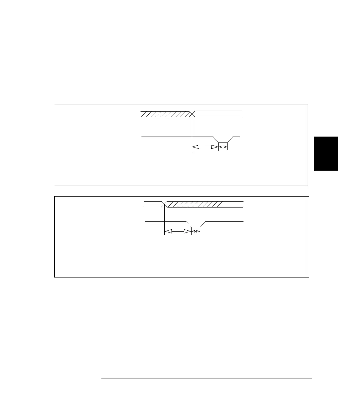
Read and Write Strobe Mode #4
Read and Write Strobe Mode #4 uses the I/O direction line as a Strobe
pulse to indicate writing operations. The PCTL line is used to indicate
Read operations. It is thus similar to the R/W and Strobe Mode #3 except
separate control lines are used for the Strobe pulses and there is no I/O
direction line.
DATA VALID
DATA LINES
Write Operation
IO DIRECTION (WR)
t1
40 µs
t2
20 µs
t1 = Time from data
valid to write
Strobe
t2 = Strobe pulse width
(20
µs
minimum)
The IO Direction line is used to indicate that the data is valid on the data bus lines.
IO Direction is used to trigger the receiving device.
(40
µs
minimum)
DATA LINES
Read Operation
PCTL (RD) LINE
t1
100 µs
t2
20 µs
t1 = Time from output
disable to read
Strobe (100
µs
t2 = Strobe pulse width
(20
µs
minimum)
DATA VALID
As in Mode #3, the PCTL (RD) line is used to indicate to the sending
device that the 3499A/B/C has latched (read) the data.
minimum)
 Loading...