100
Chapter 4 Features and Functions
Digital I/O Operation
4
Read or Write and Strobe Mode #3
In this mode, the I/O direction line is still used to indicate direction of
transfer (input or output) but the PCTL (Peripheral control) line is used
to strobe the data.
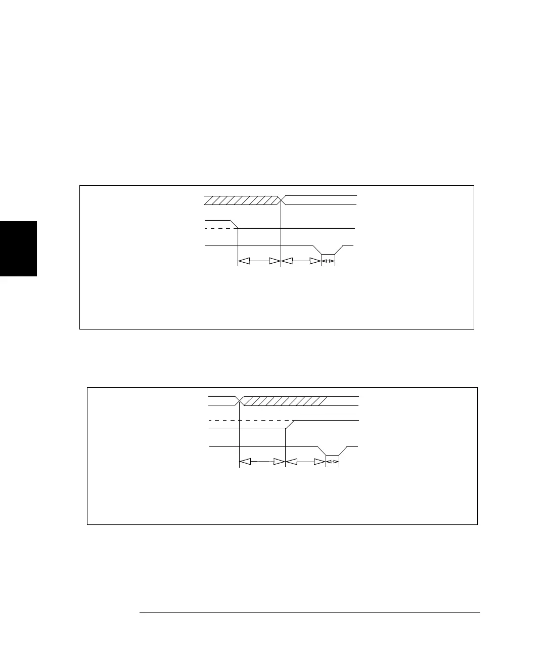
During a write operation, where the 3499A/B/C writes the data to some
external device, the strobe pulse signifies that the data on the 16 or 32
data I/O lines is valid. This is shown in the following timing diagram.
The Strobe pulse is used during a read operation to signify that the
3499A/B/C has completed the read operation. This is shown in the
following diagram.
DATA VALID
DATA LINES
I/O DIRECTION
t1 = Time from I/O line
low to output enable
Write Operation
STROBE (PCTL LINE)
t1
1ms
t2
25
µ
s
t3
20
µ
s
(1 ms minimum)
t2 = Time from output
enable to start of
s
trobe (25
µ
s
t3 = Strobe pulse width
(20
µ
s
minimum)
minimum)
A Strobe pulse signifies that the data on the data lines is valid. During a
write operation, the device receiving the data is triggered by the strobe.
DATA LINES
I/O DIRECTION
t1 = Time from output
disable to I/O line
Read Operation
STROBE (PCTL LINE)
t1
100
µ
s
t2
150
µ
s
t3
20
µ
s
high (100
µ
s min)
t2 = Time from I/O line
high to start of
Strobe (150
µ
s
t3 = Strobe pulse width
(20
µ
s
minimum)
When used during a Read operation, the Strobe pulse signifies that the
3499A/B/C has latched (read) the data from the data lines.
DATA VALID
minimum)
 Loading...