99
Chapter 4 Features and Functions
Digital I/O Operation
4
4
Static Mode #1
Static Mode #1 is the default mode. In this mode, data is transferred
statically, there is no read or write strobe pulses or handshaking. The I/O
Direction line is active and indicates direction of transfer. This is shown
in the following timing diagrams.
Static Mode #2
Static Mode #2 acts just like Mode #1 except the output lines are not
disabled during an input operation. This means that if a port is written
to and then read from, the data read will be that which was just written
to it. It is possible, however, that external devices might load the lines
and cause a false read.
Timing for the I/O direction line is as shown in Mode #1 for write
operations. For read operations, the I/O direction line does not change.
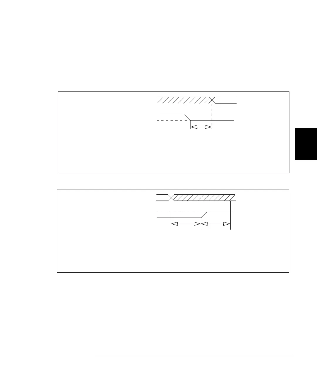
DATA VALID
DATA LINES
I/O DIRECTION
t1 = I/O input to data
valid (1ms minimum)
t1 (>1ms)
Write Operation
(CLOSE, DWRITE, etc.)
Approximately 1 ms after the I/O direction line goes to a low
state, the digital I/O module takes control of the data lines.
DATA VALID
DATA LINES
I/O DIRECTION
t1 = Data bus floated
Read Operation
(DREAD, etc.)
t1 t2
100µs150µs
to I/O input
(
100
µ
s minimum)
t2 = I/O input to data
latched (150
µ
s
minimum)
100 µs after the 3499A/B/C is instructed to read the data lines, it releases
control of the lines and the I/O direction line goes to a high state. 150 µs
later the data is actually read (latched).
 Loading...