EasyManua.ls Logo

Agilent Technologies Agilent 3499A User Manual

Agilent Technologies Agilent 3499A
357 pages
To Next Page IconTo Next Page
To Previous Page IconTo Previous Page
Page #98 background imageLoading...
Page #98 background image
98
Chapter 4 Features and Functions
Digital I/O Operation
4
About Flow Control Modes (Handshake)
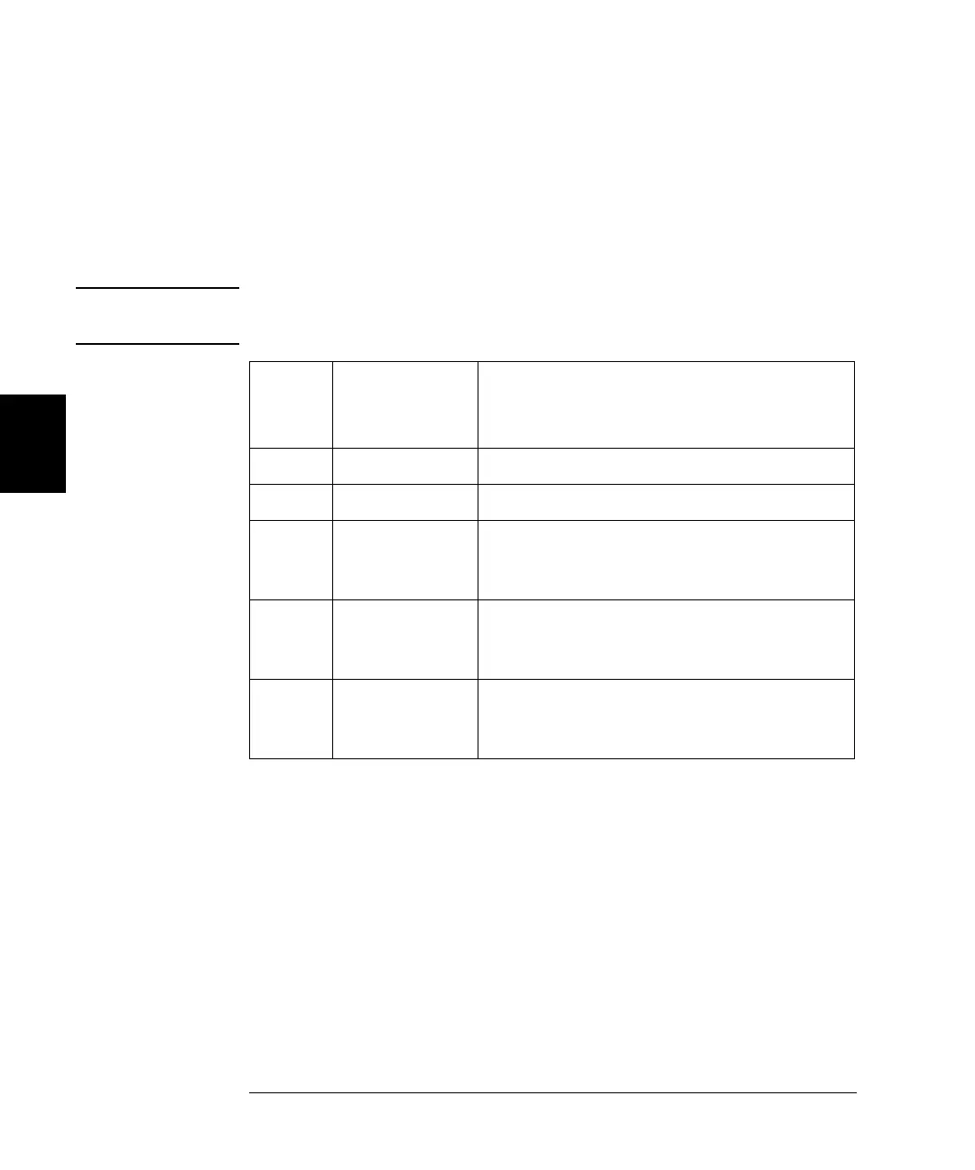
Five flow control modes are available for Digital I/O operations. Some
modes use one or more of the three flow control lines: I/O Direction,
PFLG, and PCTL. Select the flow control you need for your digital input/
output applications.
Note The polarity of the flow control lines is assumed to be positive (the
default) in the following diagrams and discussions.
Mode
Number
Handshake
Mode
Definition
Notes
1 Static mode #1 Default handshake mode.
2 Static mode #2 Read what was written.
3 Read or Write
and strobe
If you set a port to this mode, you cannot use
the port in a scan list or use card pairing
(ROUTe:CPAir).
4 Read and write
strobe
If you set a port to this mode, you cannot use
the port in a scan list or use card pairing
(ROUTe:CPAir).
5 Full handshake If you set a port to this mode, you cannot use
the port in a scan list or use card pairing
(ROUTe:CPAir).

Table of Contents

Question and Answer IconNeed help?

Do you have a question about the Agilent Technologies Agilent 3499A and is the answer not in the manual?

Agilent Technologies Agilent 3499A Specifications

General IconGeneral
BrandAgilent Technologies
ModelAgilent 3499A
CategoryControl Systems
LanguageEnglish

Summary

Chapter 1 Quick Start

Preparing the Instrument for Use

Essential steps for initial setup, including checking supplied items and powering on the instrument.

Installing Plug-in Modules

Procedure for installing and removing modules into the mainframe, including safety precautions.

Chapter 2 Front-Panel Operation

Powering On and Monitoring Instrument Status

How to turn on the instrument and monitor channel or slot status.

Scanning Operation and List Management

Steps to create, perform, and clear scan lists for automated measurements.

Instrument Error Handling and Self-Test

How to view instrument errors and perform a self-test for verification.

Chapter 3 System Overview

Channel and Slot Addressing Scheme

Explanation of how channels and slots are addressed for programming.

Chapter 4 Features and Functions

Relay Channel Switching and Multiplexer Configuration

How to switch relay channels and configure multiplexer modules.

Chapter 5 Remote Interface Reference

Chapter 6 Error Messages

Chapter 9 Specifications