215
Chapter 7 Plug-in Modules
N2272A 1 GHz RF 1-to-9 MUX Module
4
7
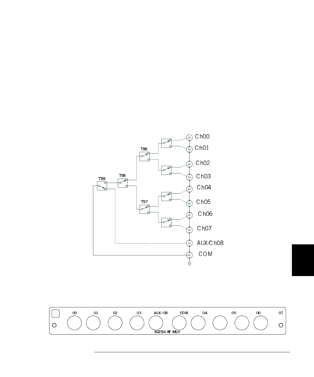
N2272A Simplified Schematic
A simplified schematic is shown below. The N2272A consists of series of
latching RF relays arranged in a tree structure. One common channel
(COM) and nine branch channels (numbered as CH00 through CH08)
are included in the N2272A. CH08 is also called an auxiliary channel
and can be used to expand channel count by connecting to another
N2272A. CH08 passes through only one relay and has a very short PC
board trace to provide smaller insertion loss and lower VSWR than the
other channels. Only one channel can be closed at a time. In addition to
the channel relays, you can also query the relay cycle count of the tree
relays (T96, T97, T98, and T99).
N2272A Wiring Information
The rear panel of the N2272A contains 10 female BNC connectors.
h00
Ch01
Ch02
Ch03
Ch04
Ch05
Ch06
Ch07
AUX/Ch08
COM
T99
T98
T97
T96
N2272A RF MUX
00 01 02 03 AUX/08 COM 04 05 06 07
 Loading...