216
Chapter 7 Plug-in Modules
N2272A 1 GHz RF 1-to-9 MUX Module
7
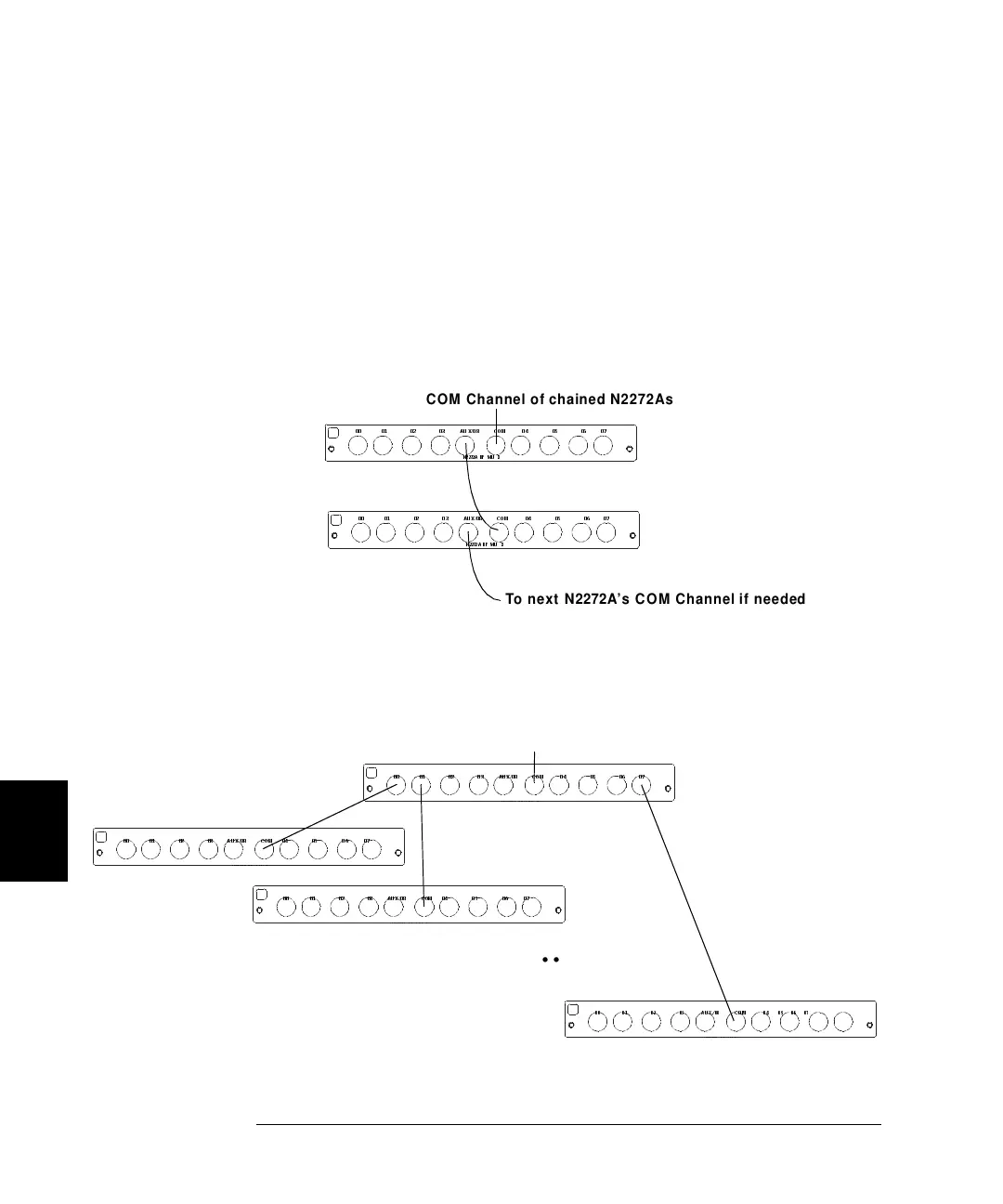
Connecting Multiple N2272A’s
The figure below illustrates how to connect two or more N2272A’s
together to form larger channel count multiplexers. Additional N2272A’s
are added by connecting each COM to the low insertion loss/low VSWR
auxiliary channel on the first N2272A.The example below, shows a 1-to-
16 multiplexer. Channel 00 through 07 are on the first N2272A, and
channel 08 through 15 are on the second N2272A. Switch the first
N2272A COM to AUX/08 to access the second bank of multiplexer
channels. Additional multiplexers can be added as necessary.
You can also connect multiple N2272A’s in a tree structure to implement
high channel count multiplexers, however, this configuration will cause
signal delays.
N2272A RF MU X
00 01 02 03 AU X/08 CO M 04 05 06 07
N2272A RF MU X
00 01 02 03 AU X/08 CO M 04 05 06 07
To next N2272A’s COM Channel if needed
COM Channel of chained N2272As
00 01 02 03 AU X/08 CO M 04 05 06 07
......
COM Channel of tree-combined N2272As
00 01 02 03 AUX /08 CO M 04 05 0 6 07
00 01 02 03 AUX /08 CO M 04 05 0 6 07
00 01 02 03 AUX/08 COM 04 05 06 07
 Loading...