231
Chapter 7 Plug-in Modules
44470A 10-Channel MUX Module
4
7
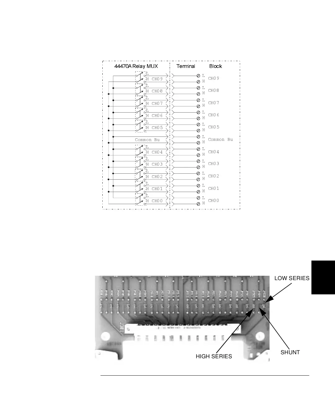
Custom Signal Conditioning
The 44470A circuit board has provision that allow you to install simple
attenuators or filter networks. Three circuit pads in each relay path are
provided that allow you to install components in the signal Hi path, Lo
path, or as a shunt from Hi to Lo. The figure below shows the 44470A
circuit board locations where components can be installed.
Common Bu
CH09
CH08
CH06
CH04
CH03
CH01
CH00
CH05
Common Bu
CH02
H
L
H
L
H
L
H
L
H
L
H
L
H
L
L
H
L
H
L
H
L
H
CH07
H CH00
L
H CH09
L
H CH08
L
H CH06
L
H CH04
L
H CH03
L
H CH01
L
L
H CH05
L
H CH02
L
H CH07
44470A Relay MUX Terminal Block
LOW SERIES
HIGH SERIES
SHUNT
 Loading...